Content .. 2057 2058 2059 2060 ..
Hummer H2. Manual - part 2059
z
A malfunctioning I/P module
z
A malfunctioning SDM
Thoroughly inspect the wiring and the connectors. An incomplete inspection of the wiring and the connectors
may result in a misdiagnosis, causing a part replacement with the reappearance of the malfunction. If an
intermittent malfunction exists, refer to Testing for Intermittent Conditions and Poor Connections in Wiring
Systems.
Test Description
The numbers below refer to the step numbers on the diagnostic table.
4: Tests to see if the malfunction is caused by the I/P module.
6: Tests to see what DTCs are present. If DTC B0016 is present, test the I/P module for a short between
high and low circuits. If DTC B0017 is present, test the I/P module high and low circuits for an open and
for high resistance. If DTC B0018 is present, test the I/P module high and low circuits for a short to
ground and for a short to voltage.
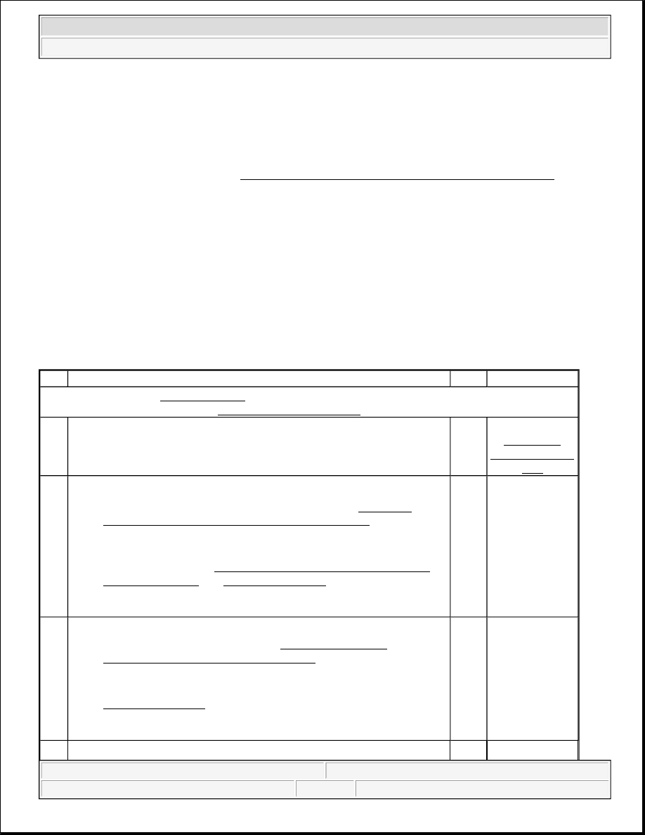
DTC B0016, B0017, or B0018
Step
Action
Yes
No
Schematic Reference:SIR Schematics
Connector End View Reference:SIR Connector End Views
1
Did you perform A Diagnostic System Check - SIR?
Go to
Step
2
Go to
Diagnostic
System Check -
SIR
2
1. Turn OFF the ignition.
2. Disconnect I/P module in-line connector. Refer to Inflatable
Restraint Instrument Panel Module Replacement .
3. Inspect the component and harness sides of the in-line connector for
the I/P module for damage or corrosion that may cause the
malfunction. Refer to Testing for Intermittent Conditions and
Poor Connections and Connector Repairs in Wiring Systems.
Does connectors exhibit any signs of damage or corrosion?
Go to
Step
3
Go to Step 4
3
1. If the in-line connector for the IP module is damaged, the I/P
module must be replaced. Refer to Inflatable Restraint
Instrument Panel Module Replacement .
2. If the wiring harness side of the I/P module in-line connector is
damaged, replace the harness side of the connector. Refer to
Connector Repairs in Wiring Systems.
Did you complete the repair?
Go to
Step
9
-
1. Use the J 38715-100 adapter to connect the J 38715-A SIR
2004 Hummer H2
2004 RESTRAINTS SIR - Hummer H2