Hummer H2. Manual - part 197
z
The identification of any stored diagnostic trouble codes DTCs and their status
The use of the Diagnostic System Check will identify the correct procedure for diagnosing the system and
where the procedure is located.
DIAGNOSTIC SYSTEM CHECK - RETAINED ACCESSORY POWER
Test Description
The numbers below refer to the step numbers on the diagnostic table.
2: Lack of communication may be due to a partial malfunction of the class 2 serial data circuit or due to a
total malfunction of the class 2 serial data circuit. The specified procedure will determine the particular
condition.
3: This step tests for valid system power moding in all ignition switch positions.
5: The presence of DTCs which begin with "U" indicate some other module is not communicating. The
specified procedure will compile all the available information before tests are performed.
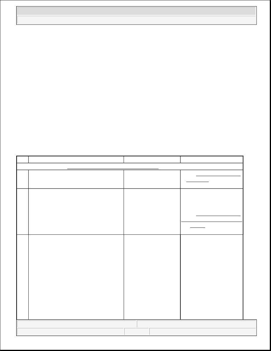
Diagnostic System Check - Retained Accessory Power
Step
Action
Yes
No
Schematic Reference:Data Link Connector (DLC) Schematics in Data Link Communications
1
Install a scan tool.
Does the scan tool power up?
Go to Step 2
Go to Scan Tool Does Not
Power Up in Data Link
Communications
2
1. Turn ON the ignition, with the
engine OFF.
2. Attempt to establish communication
with the body control module.
Does the scan tool communicate with the
body control module?
Go to Step 3
Go to Scan Tool Does Not
Communicate with Class 2
Device in Data Link
Communications
3
1. Access the class 2 power mode
IMPORTANT:
Open the driver door and leave it open
during this test. This will disable the RAP
power mode and eliminate this power
mode from the power mode parameter
list.
IMPORTANT:
The engine may start during the
following step. Turn OFF the engine as
soon as you have observed the Crank
power mode.
2004 Hummer H2
2004 ACCESSORIES & EQUIPMENT Retained Accessory Power - Hummer H2