Hummer H2. Manual - part 1378


  Index      Hummer     Hummer H2 - service repair manual 2004 year


Search            


Content   ..  1376  1377  1378  1379   ..


Hummer H2. Manual - part 1378


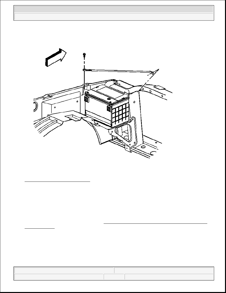
Fig. 123: Left Fender Upper Brace 
Courtesy of GENERAL MOTORS CORP. 

11. Install the fender upper brace.  

12. Install the 4 fender upper brace bolts. 

Tighten: Tighten the 4 retaining bolts to 25 N.m (18 lb ft). 

13. Connect the negative battery cable. Refer to Battery Negative Cable Disconnect/Connect Procedure 

(Single Battery) in Engine Electrical.  

14. Start vehicle and ensure all components function properly.  

INSTRUMENT PANEL ELECTRICAL CENTER OR JUNCTION BLOCK REPLACEMENT - LEFT 

Removal Procedure 


2004 Hummer H2 

2004 ACCESSORIES & EQUIPMENT Wiring Systems - Hummer H2


Fig. 124: Left Side End Panel 
Courtesy of GENERAL MOTORS CORP. 

1. Remove the left side end panel.  

2. Remove the knee bolster. Refer to Trim Panel Replacement - Knee Bolster in Instrument Panel, 

Gauges and Console.  

3. Disconnect all the wiring connectors from the fuse block.  

4. Remove all the fuses.  

5. Remove the turn signal relay from the back of the fuse block.  

6. From behind the fuse block, remove the retaining bolt.  

7. Insert a screw driver between the fuse block and the wire harness block to separate.  

8. Push on the retainers in order to remove the fuse block.  

9. Remove the fuse block from the vehicle.  

Installation Procedure 


2004 Hummer H2 

2004 ACCESSORIES & EQUIPMENT Wiring Systems - Hummer H2


1. Install the fuse block onto the IP assembly till it clicks in place.  

2. Install the wire harness block to the back of the fuse block. 

3. Install the bolt. 

Tighten: Tighten the bolt to 6 N.m (53 lb in). 

4. Install the turn signal relay to the back of the fuse block.  

5. Using the wiring diagram on the cover of the fuse panel, install the fuses.  

6. Install the electrical connectors.  

7. Install the knee bolster. Refer to Trim Panel Replacement - Knee Bolster in Instrument Panel, Gauges 

and Console. 

Fig. 125: Left Side End Panel 

NOTE:

Refer to Fastener Notice in Cautions and Notices.


2004 Hummer H2 

2004 ACCESSORIES & EQUIPMENT Wiring Systems - Hummer H2


Courtesy of GENERAL MOTORS CORP.

8. Install the left side end panel.  

INSTRUMENT PANEL ELECTRICAL CENTER OR JUNCTION BLOCK REPLACEMENT - RIGHT

Removal Procedure 

1. Remove the right side end panel.  

2. Push in the tabs in order to remove the fuse block. 

Fig. 126: Fuse Block & I/P 
Courtesy of GENERAL MOTORS CORP.


2004 Hummer H2 

2004 ACCESSORIES & EQUIPMENT Wiring Systems - Hummer H2


Content   ..  1376  1377  1378  1379   ..