Hummer H2. Manual - part 1277


  Index      Hummer     Hummer H2 - service repair manual 2004 year


Search            


Content   ..  1275  1276  1277  1278   ..


Hummer H2. Manual - part 1277


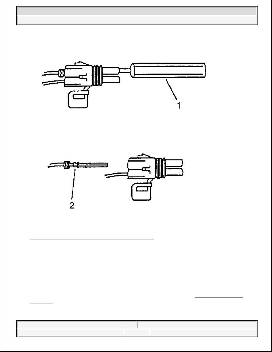
Fig. 38: Removing Cable & Terminal From Connector 
Courtesy of GENERAL MOTORS CORP. 

4. Insert the Weather Pack(R) terminal removal tool into the front (mating end) of the connector cavity until 

it rests on the cavity shoulder (1).  

5. Gently pull on the wire to remove the terminal through the back of the connector (2). 

6. Inspect the terminal and connector for damage. Repair as necessary. Refer to Repairing Connector 

Terminals .  

7. Reform the lock tang (2) and reset terminal in connector body.  

8. Close secondary locks and join connector halves. 

IMPORTANT: Never use force to remove a terminal from a connector.


2004 Hummer H2 

2004 ACCESSORIES & EQUIPMENT Wiring Systems - Hummer H2


9. Verify that circuit is complete and working satisfactorily.  

10. Perform system check.  

REPAIRING CONNECTOR TERMINALS 

Tools Required 

J-38125 Terminal Repair Kit. See Special Tools and Equipment . 

Repairing Connector Terminals 

Use the following repair procedures in order to repair the following: 

z

Push to Seat terminals  

z

Pull to Seat terminals  

Some terminals do not require all of the steps shown. Skip the steps that do not apply for your terminal repair. 
The J-38125 contains further information. See Special Tools and Equipment . 

1. Cut off the terminal between the core and the insulation crimp. Minimize any wire loss. 

For cable seal terminals, remove the seal. 

2. Apply the correct cable seal per gauge size of the wire, if used. 

Slide the seal back along the wire in order to enable insulation removal. 

3. Remove the insulation.  

4. For sealed terminals only, align the seal with the end of the cable insulation.  

5. Position the strip in the terminal. 

For sealed terminals, position the strip and seal in the terminal. 

6. Hand crimp the core wings.  

7. Hand crimp the insulation wings. 

For sealed terminals, hand crimp the insulation wings around the seal and the cable. 

8. Solder all of the hand crimp terminals excepting Micro-Pack 100 .64 size. Soldering Micro-Pack 100 

World terminals may damage the terminal.  

SCHEMATIC AND ROUTING DIAGRAMS 

POWER AND GROUNDING SCHEMATIC ICONS 


2004 Hummer H2 

2004 ACCESSORIES & EQUIPMENT Wiring Systems - Hummer H2


Power and Grounding Schematic Icons 

POWER DISTRIBUTION SCHEMATICS 

Fig. 39: B+ Bus Schematic 
Courtesy of GENERAL MOTORS CORP.

Icon

Icon Definition

CAUTION:

When performing service on or near the SIR components or the SIR 
wiring, the SIR system must be disabled. Refer to SIR Disabling and 
Enabling Zones. Failure to observe the correct procedure could cause 
deployment of the SIR components, personal injury, or unnecessary 
SIR system repairs.


2004 Hummer H2 

2004 ACCESSORIES & EQUIPMENT Wiring Systems - Hummer H2


Fig. 40: ACCY/RUN/START, RUN, and START Bus Bars, and CRANK Fuse Schematic 
Courtesy of GENERAL MOTORS CORP.


2004 Hummer H2 

2004 ACCESSORIES & EQUIPMENT Wiring Systems - Hummer H2


Content   ..  1275  1276  1277  1278   ..