Hummer H2. Manual - part 1276


  Index      Hummer     Hummer H2 - service repair manual 2004 year


Search            


Content   ..  1274  1275  1276  1277   ..


Hummer H2. Manual - part 1276


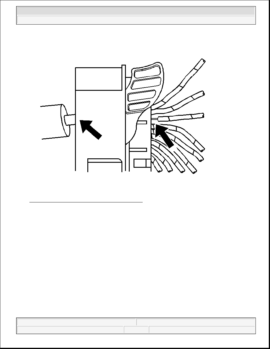
Fig. 34: Removing Wire From Back Of Connector 
Courtesy of GENERAL MOTORS CORP. 

8. While holding the removal tool in place, gently pull the wire out of the back of the connector. Always 

remember never use force when pulling a terminal out of a connector.  

Terminal Repair Procedure 

Follow the steps below in order to repair Micro 64 connector terminals. 

The Micro 64 connectors have small terminals that are difficult to handle and hold when crimping. In order to 
aid the technician when crimping these terminals, a new crimping tool was developed. The J 38125-64 (M jaw) 
was developed to crimp Micro 64 terminals. The J 38125-64 crimping tool has a terminal holding block that 
will hold the terminal in place while the terminal is being crimped. The J 38125-64 crimping tool is also 
designed to crimp both the wire and the insulation at the same time. 

After the terminal is removed from the connector perform the following procedure in order to repair Micro 64 
terminals. 

IMPORTANT: After cutting the damaged terminal from the wire, determine if the remaining 


2004 Hummer H2 

2004 ACCESSORIES & EQUIPMENT Wiring Systems - Hummer H2


1. Cut the wire as close to the damaged terminal as possible.  

2. Strip 5 mm (3/16 in) of insulation from the wire. 

Fig. 35: Identifying Crimping Tool Spring Loaded Locator 
Courtesy of GENERAL MOTORS CORP. 

3. Depress the spring loaded locator of the crimping tool until the terminal holder is completely visible. 

wire is long enough to reach the connector without putting a strain on the wire. 
If the wire is not long enough, splice a small length of the same gauge wire to 
the existing wire, then crimp the new terminal on the added wire.


2004 Hummer H2 

2004 ACCESSORIES & EQUIPMENT Wiring Systems - Hummer H2


Fig. 36: Inserting Terminal Into Terminal Holder 
Courtesy of GENERAL MOTORS CORP. 

4. Insert terminal into the appropriate terminal holder until it hits bottom and stops. The correct terminal 

holder is determined by the wire size. Also ensure that the terminals wings are pointing towards the 
former on the tool and the release locator.  

5. Insert the stripped cable into the terminal. Insulation should be visible on both sides of the terminal 

insulation wings.  

6. Compress the handles until the ratchet automatically releases. 


2004 Hummer H2 

2004 ACCESSORIES & EQUIPMENT Wiring Systems - Hummer H2


7. Place the terminal into the appropriate cavity and assemble the connector.  

WEATHER PACK CONNECTORS 

The following is the proper procedure for the repair of Weather Pack(R) Connectors. 

Fig. 37: Separating Weather Pack Connector Halves 
Courtesy of GENERAL MOTORS CORP. 

1. Separate the connector halves (1).  

2. Open the secondary lock. A secondary lock aids in terminal retention and is usually molded to the 

connector (1).  

3. Grasp the wire and push the terminal to the forward most position. Hold the wire in this position. 


2004 Hummer H2 

2004 ACCESSORIES & EQUIPMENT Wiring Systems - Hummer H2


Content   ..  1274  1275  1276  1277   ..