Hummer H2. Manual - part 1270


  Index      Hummer     Hummer H2 - service repair manual 2004 year


Search            


Content   ..  1268  1269  1270  1271   ..


Hummer H2. Manual - part 1270


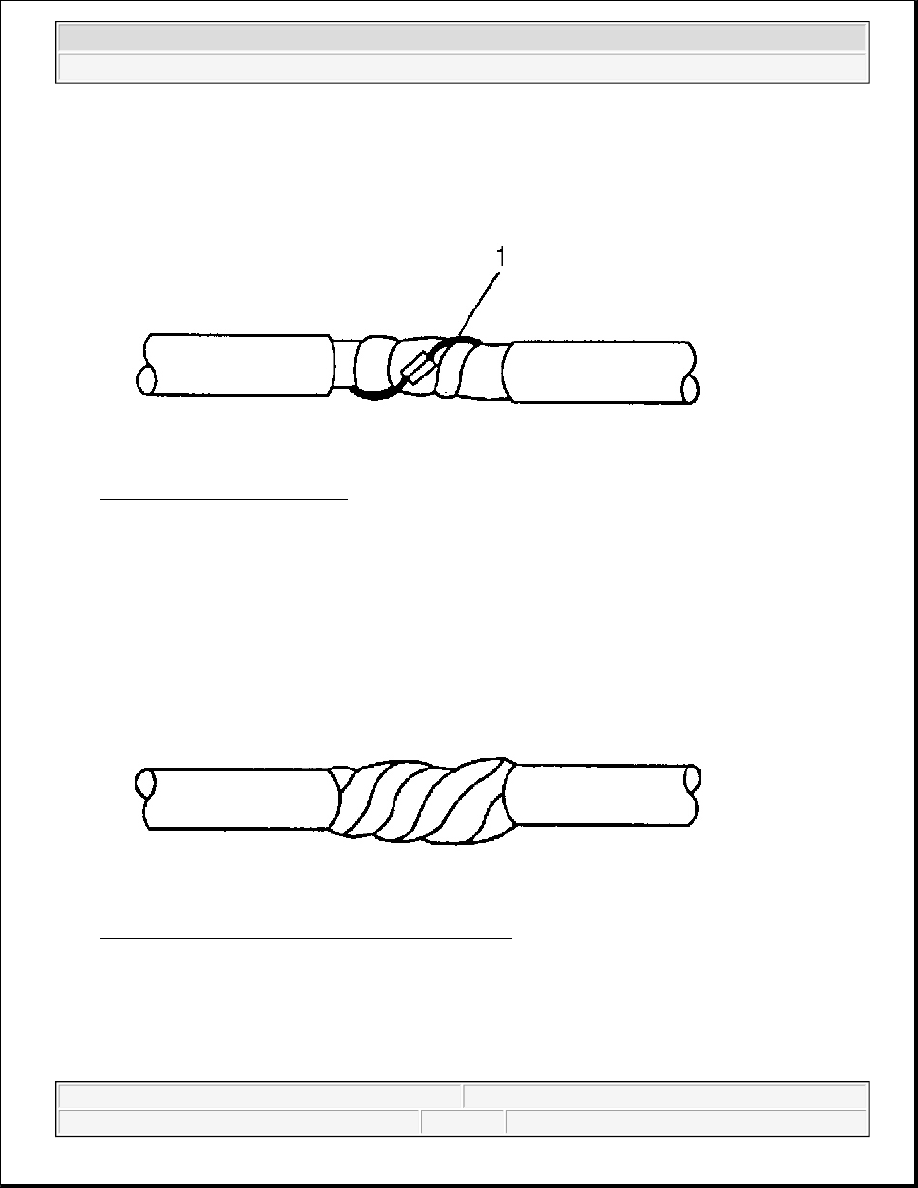
Fig. 13: View Of Diode On Wire 
Courtesy of GENERAL MOTORS CORP. 

4. Re-assemble the cable. 

z

Rewrap the conductors with the mylar tape.  

z

Use caution not to wrap the drain wire in the tape (1).  

z

Follow the splicing instructions for copper wire and splice the drain wire.  

z

Wrap the drain wire around the conductors and tape with mylar tape.  

Fig. 14: Repaired Wire Covered With Electrical Tape 
Courtesy of GENERAL MOTORS CORP. 

5. Tape over the entire cable. Use a winding motion when you apply the tape.  

SPLICING INLINE HARNESS DIODES 

Many vehicle electrical systems use a diode to isolate circuits and protect the components from voltage spikes. 

electrical contact with the drain wire.


2004 Hummer H2 

2004 ACCESSORIES & EQUIPMENT Wiring Systems - Hummer H2


When installing a new diode use the following procedure.

1. Open the harness. 

z

If the harness is taped, remove the tape.  

z

To avoid wiring insulation damage, use a sewing ripper in order to cut open the harness.  

z

If the harness has a black plastic conduit, pull out the diode.  

2. If the diode is taped to the harness, remove all of the tape.  

3. Check and record the current flow direction and orientation of diode.  

4. Remove the inoperative diode from the harness with a suitable soldering tool. 

5. Carefully strip away a section of insulation next to the old soldered portion of the wire(s). Do not remove 

any more than is needed to attach the new diode.  

6. Check current flow direction of the new diode, being sure to install the diode with correct bias. Reference 

the appropriate service manual wiring schematic to obtain the correct diode installation position.  

7. Attach the new diode to the wire(s) using 60/40 rosin core solder. Before soldering attach some heat sinks 

(aluminum alligator clips) across the diode wire ends to protect the diode from excessive heat. Follow the 
manufacturer's instruction for the soldering equipment.  

8. Reinstall terminal(s) into the connector body if previously removed. 

9. Tape the diode to the harness or connector using electrical tape.  

SIR/SRS WIRING REPAIRS 

Tools Required 

J-38125 Terminal Repair Kit. See Special Tools and Equipment . 

The Supplemental Inflatable Restraint (SIR) System/Supplemental Restraint System (SRS) requires special 
wiring repair procedures due to the sensitive nature of the circuitry. Follow the specific procedures and 
instructions when working with the SIR/SRS system wiring, and the wiring components (such as connectors 
and terminals). 

The tool kit J-38125 contains the following items:. See Special Tools and Equipment . 

IMPORTANT: If the diode is located next to a connector terminal remove the terminal(s) 

from the connector to prevent damage from the soldering tool.

IMPORTANT: To prevent shorts to ground and water intrusion, completely cover all 

exposed wire and diode attachment points with tape.

IMPORTANT: Do not use the terminals in the kit in order to replace damaged SIR/SRS system 

terminals unless specifically indicated by the terminal package.


2004 Hummer H2 

2004 ACCESSORIES & EQUIPMENT Wiring Systems - Hummer H2


z

Duraseal splice sleeves-In order to repair the SIR/SRS system wiring  

z

A wire stripping tool  

z

A special crimping tool  

z

A heat torch  

z

An instruction manual  

The duraseal splice sleeves have the following 2 critical features: 

z

A special heat shrink sleeve environmentally seals the splice. The heat shrink sleeve contains a sealing 
adhesive inside.  

z

A cross hatched (knurled) core crimp provides necessary contact integrity for the sensitive, low energy 
circuits.  

The J-38125 also serves as a generic terminal repair kit. See Special Tools and Equipment . The kit contains 
the following items: 

z

A large sampling of common electrical terminals  

z

The correct tools in order to attach the terminals to the wires  

z

The correct tools in order to remove the terminals from the connectors  

SIR/SRS Connector (Plastic Body and Terminal Metal Pin) Repair 

Use the connector repair assembly packs in order to repair the damaged SIR/SRS wire harness connectors and 
the terminals. Do not use the connector repair assembly pack in order to repair the pigtails. These kits include 
an instruction sheet and the duraseal splice sleeves. Use the duraseal splice sleeves in order to splice the new 
wires, connectors, and terminals to the harness. The splice crimping tool is color keyed in order to match the 
splices from the J-38125 . You must use the splice crimping tool in order to apply these splices. See Special 
Tools and Equipment
 . 

The terminals in the SIR/SRS system are made of a special metal. This metal provides the necessary contact 
integrity for the sensitive, low energy circuits. These terminals are only available in the connector repair 
assembly packs. Do not substitute any other terminals for those in the assembly packs. 

If the individual terminals are damaged on the sensing and diagnostic module (SDM) harness connector, use 
one of the following 2 components in order to replace the SDM harness connector: 

z

The SDM harness connector pigtail assembly  

z

The SDM harness connector replacement kit  

If the individual terminals are damaged on any other SIR/SRS connection, use the appropriate connector repair 
assembly pack in order to replace the entire connection. Replace the entire SIR/SRS wiring harness, if needed, 
in order to maintain SIR/SRS circuit integrity. 

SIR/SRS Wire Pigtail Repair 


2004 Hummer H2 

2004 ACCESSORIES & EQUIPMENT Wiring Systems - Hummer H2


A wire pigtail is a wire or wires attached directly to the device (not by a connector). If a wiring pigtail is 
damaged, you must replace the entire component (with pigtail). The inflatable restraint steering wheel module 
coil is an example of a pigtail component. 

SIR/SRS Wire Repair 

If any wire except the pigtail is damaged, repair the wire by splicing in a new section of wire of the same gauge 
size (0.5 mm, 0.8 mm, 1.0 mm etc.). Use the duraseal splice sleeves and splice crimping tool from the J-38125 
Use the following wiring repair procedures in order to ensure the integrity of the duraseal splice sleeves. See 
Special Tools and Equipment . 

SIR/SRS Wiring Repairs 

1. Open the harness by removing any tape: 

z

Use a sewing seam ripper (available from sewing supply stores) in order to cut open the harness in 
order to avoid wire insulation damage.  

z

Use the duraseal splice sleeves on all types of insulation except tefzel and coaxial.  

z

Do not use the crimp and duraseal splice sleeve to form a splice with more than 2 wires coming 
together.  

2. Cut as little wire off the harness as possible. You may need the extra length of wire in order to change the 

location of a splice. 

Adjust splice locations so that each splice is at least 40 mm (1.5 in) away from the other splices, harness 
branches, or connectors. 

3. Strip the insulation: 

IMPORTANT: Do not make wire, connector, or terminal repairs on components with wire 

pigtails.

IMPORTANT: Refer to Wiring Repairs in order to determine the correct wire size for the 

circuit you are repairing. You must obtain this information in order to ensure 
circuit integrity.

Splice Sleeve Color

Crimp Tool Nest Color

Wire Gauge mm

2

 / (AWG)

Salmon (Yellow-Pink) 

12089189

Red (1)

0.035-0.8/(18-20)

Blue 

12089190

Blue (2)

1-2/(14-16)

Yellow 

12089191

Yellow (3)

3-5/(10-12)

IMPORTANT: You must perform the following procedures in the listed order. Repeat the 

procedure if any wire strands are damaged. You must obtain a clean strip 
with all of the wire strands intact.


2004 Hummer H2 

2004 ACCESSORIES & EQUIPMENT Wiring Systems - Hummer H2


Content   ..  1268  1269  1270  1271   ..