Hummer H1 (2006+). Manual - part 347
 

  Index      Hummer     Hummer H1 DMAX - service repair manual 2006 year


Search            


Content   ..  345  346  347  348   ..


Hummer H1 (2006+). Manual - part 347


12-64

Electrical System

_______________________________________________________

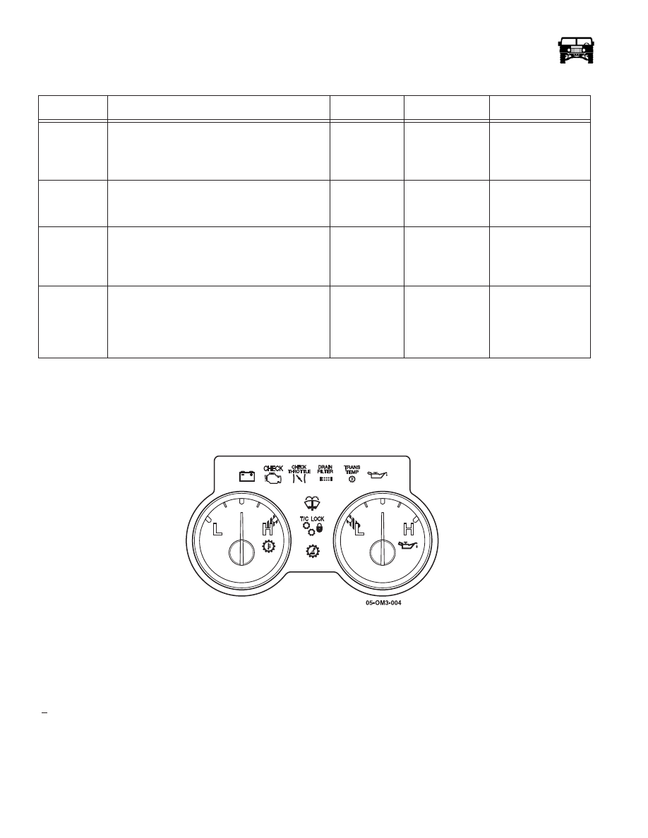
TRANSMISSION TEMPERATURE/ENGINE OIL MODULE 

The transmission temperature/engine oil module is located on the left hand side of the instrument panel (Figure 12-49). It contains
two gauges (trans temperature and oil pressure), six warning lights (low voltage, check engine, check throttle, drain filter, transmis-
sion temperature, low washer fluid and low oil pressure), and two indicator lights (T/C lock and check transmission). 

Figure 12-49:   Transmission Temperature/Engine Oil Module

Like the speedo/tach module, the only serviceable item on this module is the gauge illumination bulbs. These bulbs are removed by
turning a quarter turn counter clockwise out of the back of the module.

Warning/Indicator “Bulb Check”

When the ignition is turned to the “Run” position the “Bulb Check” should operate. The “Bulb Check” is a 4.1 second

(+ 1.0) test to see that all indicator and warning lights are functioning. If the “Bulb Check” fails to operate correctly, refer to the
bulb check diagnostic chart in this section.

Transmission Temperature/Engine Oil Module Replacement

Removal

1.

Remove the eight allen screws, and bezel around the gauge modules.

17

With a DVOM, check the continuity on circuit 
915 (LB) between the coolant/fuel module and 
the CTIS module. Does the continuity meet the 
specifications?

< 0.2 

1

Replace the cool-

ant/fuel module.

Repair circuit 915 

(LB) between the 

coolant/fuel module 

and the CTIS module.

18

Check for the “Bulb Check” signal voltage on ter-
minal 4 (CKT 912 DB). Is the specified voltage 
present?

> 12.6v

Go to step 20.

Go to step 19.

19

With a DVOM, check the continuity on circuit 
912 (DB) between the coolant/fuel module and 
the CTIS module. Does the continuity meet the 
specifications?

< 0.2 

1

Replace the cool-

ant/fuel module.

Repair circuit 912 

(DB) between the 

coolant/fuel module 

and the CTIS module.

20

With a DVOM, check the resistance on terminal 3 
(CKT 59 BK) of the CTIS module connector on 
the harness. Is the specified resistance present?

< 0.2 

1

Replace the 

CTIS module.

Repair ground circuit 

(CKT 59 BK) 

between the CTIS 

module and ground 

G4.

 “Bulb Check” Inoperative  (Figure 12-147)

Step

Action

Value(s)

Yes

No

______________________________________________________

 Electrical System  12-65

2.

Remove the four retaining screws securing the trans temperature/engine oil module  (Figure 12-50).

3.

Pull the trans temperature/engine oil module out of the instrument panel far enough to expose the harness connector.

4.

Disconnect the harness connector from the trans temperature/engine oil module.

Figure 12-50:   Trans Temp/Oil Module Removal

Installation

1.

Connect the harness connector to the trans temperature/engine oil module.

2.

Slide the module into the instrument panel and install the four retaining screws.

3.

Install the bezel, and eight allen screws.

Oil Pressure Gauge Calibration Check

To check accuracy of the oil pressure gauge use the calibration chart above. The gauge panel must be connected to the harness to
verify oil pressure. Back probe the signal wire with a DVOM and check the resistance verses the gauge readings. The readings
should approximate the specifications.

The oil pressure warning light and gauge reference the same tan wire (CKT 620). If the light activation point is questionable, refer
to the chart to verify accuracy.

Warning lights for the Trans Temp/Oil Module

All the LEDs on the volt/oil module receive voltage from a control circuit built in to the module. This controller is powered up with
system voltage on the white wire (CKT 913)  (Figure 12-150). 

The warning lights are also connected to a 4.1 second bulb check. This is achieved by a voltage signal being supplied to the module
through the red wire (CKT 910). When the module receives the voltage signal it activates an internal timer which supplies a ground
to all the LEDs on the board.

 Oil Pressure Gauge Calibration Check

Reading

Input

Ascending Descending

Low

1

X

Mid. Point

50 

1

X

High

99 

1

X

 Oil Pressure Warning Light Check

Reading

Input

Status

Asc./Des.

Input Tol.

Red Band

20 

1

ON

Des.

+8

1

Gray Band

>22 

1

OFF

Asc

+8

1

12-66

Electrical System

_______________________________________________________

Low Battery Light

The low battery light is a red LED. It is controlled by a ground signal supplied by the alternator on the orange wire with a black
tracer (CKT 904).

Check Engine Light

The check engine light is a red LED. It is controlled by a ground signal supplied by the PCM on the brown wire (CKT 658).

Low Washer Fluid Light

The washer fluid light is an amber LED. It is controlled by a ground signal supplied by the low washer fluid level switch on    the
yellow wire (CKT 793). This light has been dampened with a 1.5 second delay. The purpose of this delay is to prevent the washer
fluid light from flashing when the fluid is sloshing around. When testing this circuit supply ground for a minimum of 3 seconds.

TC Lock Light

The TC lock indicator is a green LED. It is controlled by a ground signal supplied by the transfer case lock switch on the dark green
wire (CKT 210).

Check Throttle Light

The check throttle light is an amber LED. It is controlled by a ground signal supplied by the PCM on the dark blue wire (714).

Drain Filter Light

The drain filter light is an amber LED. It is controlled by a ground signal supplied by the water in filter sensor on the yellow wire
(CKT 327).

Low Oil Pressure Light

The low oil pressure light is a red LED. It is controlled by a ground signal supplied by an internal driver. This internal driver
watches the oil pressure signal on the tan wire (CKT 31). If the signal drops below 20 

1 then the driver sends a ground signal to il-

luminate the LED. The light will reset if the signal on the wire rises above 22 

1.

______________________________________________________

 Electrical System  12-67

COOLANT/FUEL MODULE

The coolant/fuel module is located on the right side of the instrument panel. In contains two gauges (coolant temperature and fuel level),
seven warning lights (high coolant temp., low coolant, brake, ABS, low fuel and ELocker) and two indictor lights (TT4) and front
ELocker  (Figure 12-51).

Figure 12-51:   Coolant/Fuel Module

Like the speedo/tach module the only serviceable items on this module are the gauge illumination bulbs. These bulbs are removed
by turning a quarter turn counterclockwise out of the back of the module.

Coolant/Fuel Module Replacement

Removal

1.

Remove the eight allen screws, and the bezel around the gauge modules.

2.

Remove the four retaining screws from the coolant/fuel module (Figure 12-52).

3.

Pull the coolant/fuel module out of the instrument panel far enough to expose the harness connector.

4.

Disconnect the harness connector from the coolant/fuel module and remove the module.

Figure 12-52:   Coolant/Fuel Module Replacement

Installation

1.

Connect the harness connector to the coolant/fuel module.

2.

Slide the module into the instrument panel and install the four retaining screws.

3.

Install the bezel, and eight allen screws.

Coolant Temperature Gauge and Warning Light Calibration Check

To check accuracy of the coolant temp gauge or light use the calibration chart. The gauge panel must be connected to the harness to
verify coolant temperature. Back probe the signal wire with a DVOM, and check the resistance verses the gauge readings. The


Content   ..  345  346  347  348   ..