Hummer H1 (2006+). Manual - part 346
 

  Index      Hummer     Hummer H1 DMAX - service repair manual 2006 year


Search            


Content   ..  344  345  346  347   ..


Hummer H1 (2006+). Manual - part 346


12-60

Electrical System

_______________________________________________________

SPEEDO/TACH MODULE

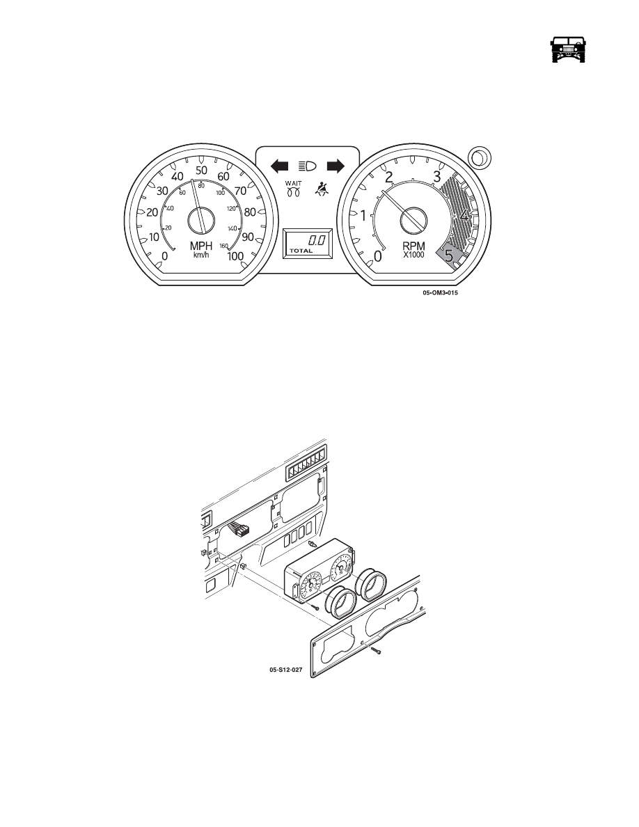
The speedo/tach module is the primary control of the three gauge modules (Figure 12-46). It controls the start up bulb test and the operat-
ing voltage that the other modules use. Main power is supplied to the speedo/tach module on circuit 30 (GY). It then sends operating volt-
age to the volt/oil module through circuit 913 (WH) and to the coolant/fuel module through circuit 916 (TN)  (Figure 12-116).

Figure 12-46:   Speedo/Tach Module

Speedo/Tach Module 

Removal

1.

Remove the eight allen screws, and the bezel from around the gauges.

2.

Remove the four retaining screws from the speedo/tach module  (Figure 12-47).

3.

Pull the speedo/tach module out of the instrument panel far enough to expose the harness connector.

4.

Disconnect the harness connector from the speedo/tach module and remove the module.

Figure 12-47:   Speedo/Tach Module Removal

Installation

1.

Connect the harness connector to the speedo/tach module.

2.

Slide the module into the instrument panel and install the four retaining screws.

3.

Install the bezel, and eight allen screws.

______________________________________________________

 Electrical System  12-61

Gauge Illumination

The only serviceable portion of the speedo/tach module is the back lighting bulbs. There are six bulbs in this module that are used for
gauge illumination only. These bulbs are easily replaced by twisting them 1/4 turn out of the back of the circuit board on the module
(Figure 12-48). The other modules are similar in repair to the speedo/tach module.

Figure 12-48:   Illumination Bulb Replacement

Circuit Description 

The speed sensor circuit consists of a magnetic induction type sensor, TCM, ECM and wiring. Geared teeth pressed on the output
shaft induce an alternating current in the sensor. This A/C signal is transmitted to the TCM. The TCM relays the signal to the ECM.
When the ECM receives the signal it compensates for various axle ratios and converts the signal into a digital signal for use by the
speedometer, cruise control, and the ELocker module. The speed signal is also used to control shift points, line pressure, TCC and
diagnostic codes. Circuit 353 sends a signal of 128K pulses per mile to the speedometer and the ELocker module  (Figure 12-142).

Speedometer Calibration Check

To check accuracy of the speedometer use the calibration chart above. The gauge panel must be connected to the harness to verify speed.
Back probe the signal wire with a DVOM, and check the hertz reading while accelerating to 30 MPH then to 60 MPH then decelerate to
30 MPH and check the reading. The readings should approximate the specifications above.

Odometer Illumination

The odometer illumination is not serviceable. Back lighting is on at all times on the odometer. The circuit that feeds power to the odome-
ter back lighting changes when the head lamp switch is in the “On” position. With the headlight switch in the “On” position the odometer
back lighting switches to illumination circuit 17 (PP). This allows the odometer back lighting to be dimmed.

Self Tests and Bulb Checks

Speedo/Tach Self test

The speedo/tack module is equipped with a self test function to   indicate proper functionality. 

 Speedometer Calibration Check

Approximate Reading

Input

Ascending

Descending

30 MPH

33.33 Hz

X

60 MPH

66.67 Hz

X

30 MPH

33.33 Hz

X

12-62

Electrical System

_______________________________________________________

To preform the self test hold the “trip odometer reset button” down and turn the ignition switch to the “Run” position. A normally operat-
ing module will have the speedo gauge reading between 45-55 MPH and the tachometer between 1500-2500 RPM. The gauges should
stay in this position until the “trip odometer reset button” is released.

NOTE: The odometer will advance at a rate of 0.8 miles a minute as long as the self test is running. This is a test to see if the odometer is
functioning properly.

Warning/Indicator “Bulb Check”

The “Bulb Check” signal is a battery voltage signal sent out from the speedo/tach module for 4.1 seconds (+ 1.0 second). The purpose of
this test is to verify that all warning lights are functioning properly. The speedo/tack module sends this voltage to the volt/oil module
though circuit 910 (RD). From the volt/oil module voltage travels to the coolant/fuel module on circuit 911 (GY/BK) and then to the
CTIS module on circuit 912 (DB) (Figure 12-143).

If any of the test circuits between the modules were to have excessive resistance or an open, the module(s) after the problem may not
function properly on the “bulb check”.

For example: If circuit 911 (GY/BK) were to become open the coolant/fuel module and the CTIS module may not function properly.

Tachometer Calibration Check

To check the accuracy of the tachometer use the calibration chart above. The gauge panel must be connected to the harness to ver-
ify RPM. Back probe the signal wire with a DVOM, and check the hertz reading while accelerating to 600 RPM then to 2000 RPM
then decelerating back to 600 RPM and checking the readings. The readings should approximate the specifications above.

NOTE:  The “Bulb Check” only lasts for 4.1 seconds requiring cycling of the ignition to check the signal voltage. 

 Tachometer Calibration Check

Approximate Reading

Input

Ascending

Descending

600 RPM

43.33 Hz

X

2000 RPM

133.33 Hz

X

600 RPM

43.33 Hz

X

 “Bulb Check” Inoperative  (Figure 12-147)

Step

Action

Value(s)

Yes

No

1

Do any of the modules perform the “Bulb 
Check”?

Go to step 5.

Go to step 2.

2

Remove the speedo/tach module and disconnect 
the harness. Turn the ignition switch to the “Run” 
position. With a DVOM, check for voltage on ter-
minal 7 (CKT 30 GY) on the harness connector.
Is battery voltage present?

>12.6v

Go to step 3

Repair the open or bad 

connection on circuit 

30 (GY), between the 

speedo/tach module 

and fuse 4B of the 

interior fuse box.

3

With a DVOM, check the resistance to ground on 
terminal 14 (CKT 59 BK) on the harness connec-
tor. Does the resistance meet the specification?

< 0.2 

1

Go to step 4.

Repair the open or bad 

connection on circuit 

59 BK between the 

speedo/tach module 

and G4

4

With a DVOM, check the voltage on terminal 10 
(CKT 910 RD). Is the specified voltage present?

> 12.6v

Go to step 5.

Replace the speedo/

tach module.

5

Does the volt/oil module perform the “Bulb 
Check” when the ignition switch is cycled?

Go to step 10.

Go to step 6.

______________________________________________________

 Electrical System  12-63

6

Remove the volt/oil module and check for system 
voltage on terminal 13 (CKT 913 WH). Is system 
voltage present?

>12.6v

Go to step 8.

Go to step 7.

7

With a DVOM, check the continuity on circuit 
913 (WH) between the volt/oil module and the 
speedo/tach module. Does the continuity meet the 
specification?

< 0.2 

1

Replace the 
speedo/tach

module.

Repair circuit 913 

(WH) between the 

speedo/tach module 

and the volt/oil mod-

ule.

8

Check for the “Bulb Check” signal voltage on ter-
minal 9 (CKT 910 RD). Is the specified voltage 
present?

> 12.6v

Go to step 9.

Repair the open or bad 

connection on circuit 

910 RD between the 

speedo/tach module 

and the volt/oil mod-

ule.

9

With a DVOM, check the resistance on terminal 
14 (CKT 59 BK) of the volt/oil module connector 
on the instrument harness. Is the specified resis-
tance present?

< 0.2 

1

Replace the volt/

oil module.

Repair ground cir-

cuit (CKT 59 BK) 

between the volt/oil 

module and ground 

G4.

10

Does the coolant/fuel module perform the “Bulb 
Check” when the ignition switch is cycled?

Go to step16

Go to step 11.

11

Remove the coolant/fuel module and check for 
system voltage on terminal 13 (CKT 916 TN). Is 
system voltage present?

>12.6v

Go to step 13.

Go to step 12.

12

With a DVOM,DVOM, check the continuity on 
circuit 916 (TN) between the coolant/fuel module 
and the speedo/tach module. Does the continuity 
meet the specification?

< 0.2 

1

Replace the 
speedo/tach

module.

Repair circuit 916 

(TN) between the 

speedo/tach module 
and the coolant/fuel 

module.

13

Check for the “Bulb Check” signal voltage on ter-
minal 7 (CKT 911 GY/BK). Is the specified volt-
age present?

> 12.6v

Go to step 15.

Go to step 14.

14

With a DVOM, check the continuity on circuit 
911 (GY/BK) between the coolant/fuel module 
and the speedo/tach module. Does the continuity 
meet the specification?

< 0.2 

1

Replace the 
speedo/tach

module.

Repair circuit 911 

(GY/BK) between 

the coolant/fuel 

module and the 

speedo/tach module.

15

With a DVOM, check the resistance on terminal 
14 (CKT 59 BK) of the coolant/fuel module con-
nector on the instrument harness. Is the specified 
resistance present?

< 0.2 

1

Replace the cool-

ant/fuel module.

Repair the ground cir-

cuit (CKT 59 BK) 

between the coolant/

fuel module and 

ground G4.

16

Remove the CTIS module and check for specified 
voltage on terminal 2 (CKT 915 LB). Is system 
voltage present?

10v

Go to step 18.

Go to step 17.

 “Bulb Check” Inoperative  (Figure 12-147)

Step

Action

Value(s)

Yes

No


Content   ..  344  345  346  347   ..