Hummer H1 (2006+). Manual - part 345
 

  Index      Hummer     Hummer H1 DMAX - service repair manual 2006 year


Search            


Content   ..  343  344  345  346   ..


Hummer H1 (2006+). Manual - part 345


12-56

Electrical System

_______________________________________________________

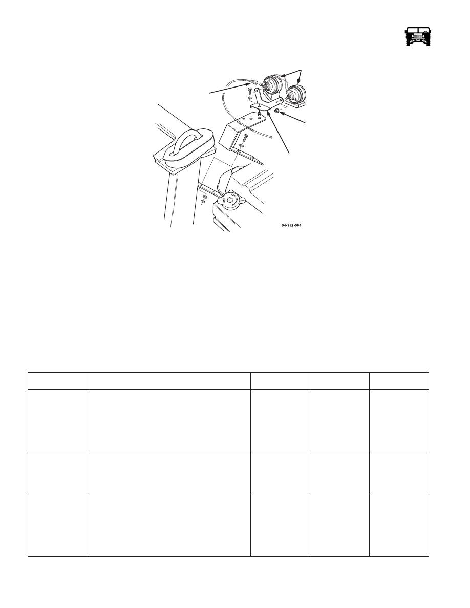
Figure 12-41:   Horn and Horn Mounting Bracket Replacement

Horn Mounting Bracket Replacement

Removal

1.

Remove the two horns.

2.

Remove the bolts, washers, lock washers, nuts, and the horn mounting bracket from the airlift bracket (Figure 12-41).

Installation

1.

Secure the horn mounting bracket to the airlift bracket with the bolts, washers, lock washers, and the nuts (Figure 12-41).

2.

Install the two horns.

 Horns Inoperative  (Figure 12-120)

Step

Action

Value Yes

No

1.

Locate the horn assemblies under the hood.
Disconnect the harness from the horn assemblies. 
With a DVOM, check the ground circuit 58 (BK) 
between pin B harness side and a good ground.
Is the ground circuit within specifications?

<.2

1

Go to step 2.

Repair the open 

or bad connection 

on CKT 58 

between the horn 

assemblies and 

G2.

2.

With a DVOM, back probe the horn circuit 6 
(WH) pin A on the horn assemblies and check for 
voltage when the horn button is pushed.
Is the specified voltage present?

+12v

Replace the horn 

assemblies.

Go to step 3.

3.

Remove the horn relay from the exterior fuse box. 
With a DVOM, check resistance between the relay 
cavity 1F and the horn circuit 6 (WH) pin A on the 
horn assemblies. 
Does the resistance meet the specifications?

<.2

1

Go to step 4.

Repair the open 

or bad connection 

in CKT 6 

between the horn 

relay and the 

horn assembly. 

MOUNTING

BRACKET

HARNESS CONNECTOR

NUT

HORN

______________________________________________________

 Electrical System  12-57

CIGARETTE LIGHTER REPLACEMENT

Removal 

1.

Remove the element from the lighter assembly heater  (Figure 12-42).

3.

Remove the heater and the bezel from the console using the cigarette lighter socket tool (J–42059).

4.

Remove the wiring harness connector from the lighter assembly

Installation

1.

Install the wiring harness connector on the lighter assembly.

2.

Install the heater in console  (Figure 12-42).

3.

Install the element in the lighter assembly.

4.

Engage the cigarette lighter to ensure proper operation.

Figure 12-42:   Cigarette Lighter Breakdown

INSTRUMENT PANEL SYSTEM DESCRIPTION

The instrument panel system includes three gauge modules, a CTIS control module and assorted control switches (Figure 12-43). 

The three gauge modules are self contained allowing minimal repair. They are equipped with an anti-fog coating on the inboard
side of the lens and an anti-scratch coating on the out board side of the lens. The warning light bulbs have been replaced with light

4.

With a DVOM, check for voltage in cavities 3E 
and 1E of the exterior fuse box. 
Is the specified voltage present?

+12v

Go to step 5.

Repair the open 

or bad connection 

in CKT 7 

between the horn 

relay and the 

exterior fuse box.

5.

With a DVOM, check the resistance to ground on 
cavity 3F, of the exterior fuse box, when the horn 
switch is pressed. 
Does the resistance meet the specifications?

<.2

1

Replace the 

horn relay.

Go to step 6.

6.

With a DVOM, back probe C1 circuit 1 (DB) pin 
12 Activate the horn switch and watch the resis-
tance on the meter. Does the resistance meet the 
specifications?

<.2

1

Repair the open 

or bad connection 

on CKT 1 

between the horn 

switch and the 

horn relay.

Replace the 

horn bottom.

 Horns Inoperative  (Figure 12-120)

Step

Action

Value Yes

No

12-58

Electrical System

_______________________________________________________

emitting diodes (LED) for clearer viewing. The CTIS module has also been improved with a domed lens to reduce glare and con-
tains LEDs for clearer viewing. 

Figure 12-43:   Instrument Panel

NOTE: When working on or around the back of the instrument panel clusters always wear a static strap. The gauge modules are
extremely sensitive to voltage and may be damaged if shocked.

Instrument Panel Switch Replacement

NOTE: All instrument panel switches are replaced similarly, with the exception of the dimmer control switch. This procedure covers the
main light switch.

CAUTION: Some connectors can be installed incorrectly and cause damage to the electrical system. Make note of connector position
prior to removal.

Removal

1.

Remove the drivers side closeout panel.

2.

Reach up behind the instrument panel and push Remove the connector from the switch (Figure 12-44).

3.

Push the switch from the switch housing.

Installation

1.

Install the switch in the switch housing.

2.

Plug the connector into the switch (fig 12-97).

3.

Install the drivers side closeout panel.

______________________________________________________

 Electrical System  12-59

Figure 12-44: Switch Replacement

Instrument Panel Dimmer Control Switch Replacement

Removal 

1.

Remove the drivers side closeout panel.

2.

Reach up behind the instrument panel, and unplug the connector from the wiring harness (Figure 12-45).

3.

Push the switch from the switch housing.

Figure 12-45:   Instrument Panel Dimmer Control Switch Replacement

Installation

1.

Install the switch in the switch housing (Figure 12-45).

2.

Plug the connector into the switch.

3.

Install the drivers side closeout panel.


Content   ..  343  344  345  346   ..