Hummer H1 (2002+). Manual - part 262


  Index      Hummer     Hummer H1 - service repair manual 2002 year


Search            


Content   ..  260  261  262  263   ..


Hummer H1 (2002+). Manual - part 262


____________________________________________________________

 Accessories  13-41

®

05745159

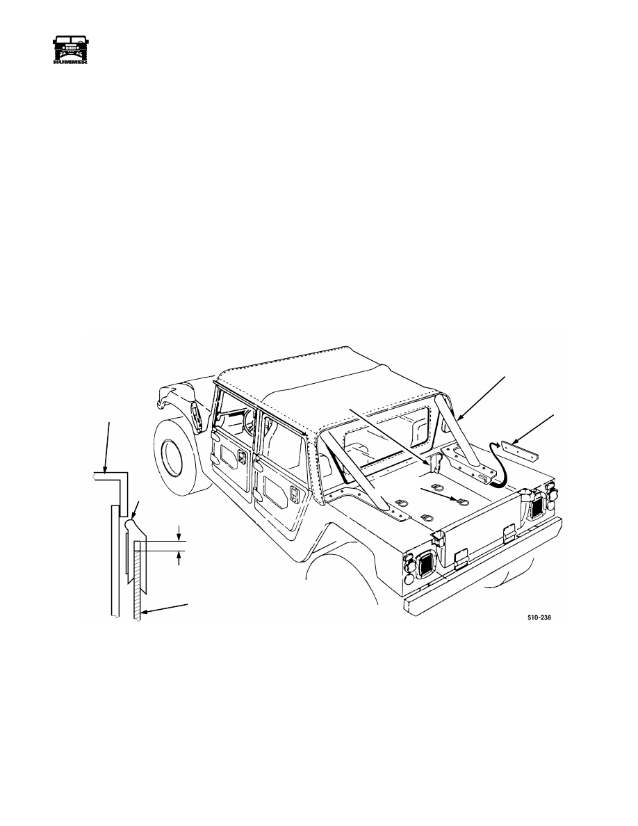
NOTE: The edge trim should not be installed over the vertical
angle brackets in the front corners of the bed.

NOTE: If you are reusing the original edge trim you will need
to install a double sided foam tape such as 3M 06382 to the
backside of the edge trim pieces.

12. Mark the lengths of edge trim to be used on the right and

left sides of the liner. Do not use edge trim under the
support tube brackets on soft top models or under the
tonneau cover bow bracket on hard top models. Once
the proper lengths of edge trim have been marked, cut
the edge trim to length. Install the edge trim onto the top
edge of the bedliner, but do not remove the adhesive film
backing yet. The edge trim must be installed loosely
onto the top edge of the bedliner. A 1/8" gap should be
left between the inside edge of the trim and the top of
the bedliner to allow for expansion.

13. When all the pieces of edge trim are in their correct

location, remove the adhesive film backing from one
piece of trim and press it into place. Repeat until all the
pieces of trim are in place.

14. Clean the vehicle tailgate. Center the tailgate cover side

to side and push the cover forward until the cover is
tight against the top of the tailgate. Using the holes in
the upper corners of the cover, mark the tailgate and drill
two 5/32" holes in the tailgate for the cover retaining
screws. Redrill the holes in the tailgate cover only out to
3/8". Fasten the tailgate cover to the tailgate by install-
ing the screws and washers. Snap a plastic cap over each
washer.

15. Clean the tailgate along the bottom edge of the cover

with rubbing alcohol to insure proper adhesion of the
edge trim. Install the edge trim leaving a 1/8" gap
between the inside edge of the trim and the cover for
expansion. Remove the adhesive film backing and press
the trim into place.

Figure 13-80:   Bedliner Installation In Soft top vehicle.

“C” PILLAR REAR

SUPPORT BAR

ANGLE

BRACKET

SHIM

TIEDOWN

LINER

EDGE

TRIM

WHEEL

HOUSE

1/8"

GAP

13-42

Accessories

_____________________________________________________________

®

REMOTE ENTRY TRANSMITTER BATTERY 
REPLACEMENT

1.

Remove the screw in the back of the transmitter


(See Figure 13-81).

2.

Using a small screw driver or a knife blade, carefully pry
the two halves of the transmitter apart exposing the
battery.

3.

New batteries can be obtained from an electronics supply
store. The battery size is 27A 12V.

4.

Carefully pry the battery out and install the new battery.
Match the polarity markings on the transmitter casing and
the battery when installing.

5.

Snap the transmitter case halves together and install the
screw in the back of the transmitter.

6.

Test the operation of the remote entry transmitter.

Figure 13-81:   Remote Entry Battery Replacement

STAINLESS STEEL FRONT BUMPER COVER 

(WITH BRUSHGAURD AND W/O WINCH)

Removal

1.

Remove two bolts and the licence plate mount bracket 
(See Figure 13-82).

2.

Remove four bolts, washers and two tow bracket/lifting
shackle assemblies.

3.

Pull the SS cover free from the bumper and clean the
double sided foam tape from the cover and bumper.

Figure 13-82:   SS Front Bumper Cover W/O Winch

Installation

1.

Clean all grease and dirt from the front bumper and cover 
and prep the surfaces with alcohol.

2.

Apply new double sided foam tape to the back of the cover
and press the cover on the bumper.

3.

Install two tow bracket/lifting shackle assemblies, four
bolts and washers. Torque the bolts to 90 lb-ft (122 N•m).

4.

Install the licence plate mounting bracket with two bolts
and torque to 8-13 lb-ft (11-18 N•m).

9-S13-017

BATTERY

SCREW

TRANSMITTER

CASE

BUMPER

SS COVER

LICENCE

BRACKET

LIFT

SHACKLE

TOW

BRACKET

____________________________________________________________

 Accessories  13-43

®

05745159

STAINLESS STEEL FRONT BUMPER COVER 

(WITH WINCH)

Removal

1.

Remove two bolts and the licence plate mount bracket 
(See Figure 13-83).

2.

Remove four bolts, washers and two tow bracket/lifting
shackle assemblies.

3.

Support the winch and remove the bolts and washers
securing the bumper to the winch.

4.

Pull the cover free from the bumper and clean the double
sided foam tape from the bumper and cover.

Figure 13-83:   SS Front Bumper Cover W/Winch

Installation

1.

Clean all grease and dirt from the front bumper and cover 
and prep the surfaces with alcohol.

2.

Apply new double sided foam tape to the back of the cover
and press the cover on the bumper.

3.

Install two tow bracket/lifting shackle assemblies, four
bolts and washers. Torque the bolts to 90 lb-ft (122 N•m).

4.

Install the winch mounting bolts and washers and torque
to 60 lb-ft (81 N•m).

5.

Install the licence plate mounting bracket with two bolts
and torque to 8-13 lb-ft (11-18 N•m).

STAINLESS STEEL REAR BUMPER COVER 

Removal

1.

Remove two bolts and the licence plate mount bracket 
(See Figure 13-84).

2.

Remove four bolts, washers and two tow bracket/lifting
shackle assemblies.

3.

Remove the bolt covers from the bolt heads.

4.

Pull the SS cover free from the bumper and clean the
double sided foam tape from the cover and bumper.

Figure 13-84:   SS Rear Bumper Cover

Installation

1.

Clean all grease and dirt from the front bumper and cover 
and prep the surfaces with alcohol.

2.

Apply new double sided foam tape to the back of the cover
and press the cover on the bumper.

3.

Install two tow bracket/lifting shackle assemblies, four
bolts and washers. Torque the bolts to 90 lb-ft (122 N•m).

4.

Install the licence plate mounting bracket with two bolts
and torque to 8-13 lb-ft (11-18 N•m).

5.

Install the bolt covers on the bolt heads.

STAINLESS

COVER

FRONT

BUMPER

TOW

BRACKET

LICENCE

BRACKET

LIFTING

SHACKLE

9-S13-019

BOLT

COVER

BUMPER

SS COVER

LIFT

SHACKLE

ASSEMBLY

13-44

Accessories

_____________________________________________________________

®

STAINLESS STEEL UPPER GRILLE COVER 
REPLACEMENT

Removal

1.

Remove the six screws, washers and nuts securing the SS 
grille frame to the original grille frame and remove the SS 
grille frame (See Figure 13-85).


Figure 13-85:   SS Upper Grille Frame R&I

2.

Peel the eight SS grille slats off from the original grill slats
and remove the double-sided tape with an adhesive
remover.

Figure 13-86:   SS Upper Grille Slat R&I

Installation

1.

Clean all the original and SS grille slats with alcohol.

2.

Place the SS grille frame over the original grille frame and
loosely install the six SS screws, washers and nuts.

3.

Use an alternate tightening sequence and torque the screws
to 7 lb-ft (9 N•m).

4.

Place two 3 inch pieces of double-sided tape on the back
side of the eight SS slats, approximately 2 inches from
each end of the slat.

5.

Starting with the bottom grille slat, peel the backing off
the double-sided tape and hook the front edge of the SS
slat on the front edge of the original slat and roll the SS
slat into place. Press and hold momentarily to ensure a
good bond.

6.

Continue installing the remaining slats noting that the
fourth slat has the tab to cover the grille mesh mounting
screw area.

STAINLESS STEEL WHEEL COVER REPLACE-
MENT

Removal

1.

Locate the two lugnut simulators that can be turned by 
hand and remove the simulators and the plastic inserts.

2.

Remove the two nuts and washers securing the wheel
cover to the mounting brackets and remove the cover.

3.

Remove the bolts, lockwashers and washers securing the
mounting brackets and CTIS tube shield (if equipped)
from the spindle and remove the brackets and shield.

Figure 13-87:   Wheel Cover Replacement

Installation

1.

Install the two wheel cover mounting brackets and CTIS 
tube shield (if equipped) on the spindle with four bolts, 
lock washers and washers. Torque the bolts to 37 lb-ft (50 
N•m).

2.

Place the wheel cover over the studs on the mounting
brackets and install the nuts and washers. Torque the nuts
to 8-13 lb-ft (11-18 N•m).

3.

Install the plastic inserts and the lug nut simulators.

SCREW

HOLE

SS

GRILLE

FRAME

SS SLAT

ROLL
INTO

PLACE

WHEEL

COVER

MOUNTING

BRACKET

LUG NUT

SIMULATOR

SPINDLE

PLASTIC

INSERT

CTIS

TUBE

SHIELD


Content   ..  260  261  262  263   ..