Hummer H1 (2002+). Manual - part 261


  Index      Hummer     Hummer H1 - service repair manual 2002 year


Search            


Content   ..  259  260  261  262   ..


Hummer H1 (2002+). Manual - part 261


____________________________________________________________


 Accessories  13-37


®


05745159


SEAT HEATER


NOTE: 


The following procedures apply to either the left or the

right front seat.


Removal


1. Disconnect two wire connectors at the lower rear of the

seat back and clip the wire ties securing the wires to the
seat frame.

2. Remove four seat retaining bolts, washers and seat from

vehicle.

3. Remove two screws at the front of the seat cushion and

remove the cushion.

4. Using a screwdriver, release the fabric retaining clips

and pull the fabric back to expose the fabric hold down
wire and hog rings. Clip the hog rings and remove the
fabric from the seat cushion (Figure 13-76).

5. Peel the heating element off the foam padding.

6. Remove two bolts, washers and the arm rest from the

seat back.

7. Remove the arm rest side hinge cover and center cover.

8. Pry the metal fabric retainer channels open on the seat

back frame and remove the fabric from the channels.

9. Remove the connector from the seat back wire harness

and pull the wires through the hole in the fabric and the
seat frame.

10. Roll the fabric up approximately 14” on both sides.

11. Remove the heating element from the foam padding of

the seat back (Figure 13-77).

12. Remove the center console cover.

13. Pull the harness through the hole in the trim panel near

the seat belt mount point. Disconnect the harness from
the switch, pull the control box from its velcro mount on
the body and remove the control box and the harness.

14. Remove the switch from the center console cover.

15. Remove the drivers side dash closeout panel.

16. Disconnect the harness from the auxilliary power point

and the instrument ground point at the left of the
steering column and remove the harness from the dash
area.


Installation


1. Installation is the reverse of the removal using new hog

rings that were clipped in step 4 and inserting the brown
wire in position “B” and the blue wire in position “A” of
the connector in step 9.


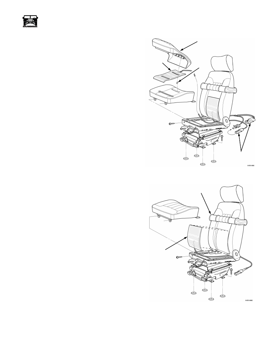
Figure 13-76:   Seat Cushion Element Removal.

Figure 13-77:   Back Element Removal.

HOG

RING

CUSHION

ELEMENT

CUSHION

FABRIC

ELECTRICAL

CONNECTIONS


BACK

ELEMENT

ROLLED

FABRIC


13-38

Accessories


_____________________________________________________________


®


Diagnostics


 Seat Heater Does Not Heat


Step

Action

Value(S)

Yes

No


1


NOTE: 


The control box contains a timer

that will shut the heater off after one hour
of use. The switch must be cycled “OFF”
and “ON” to restart the heat cycle.

Turn ignition to the “ON” position. Posi-
tion the seat heater switch to one of the
heat positions. Does the switch illumi-
nate?

Switch light 

“ON”

Go to step 2.

Check/repair fuse 3G cir-
cuit through the auxiliary 
power point to the switch 
“2B” and “3B” (red wire) 
and ground circuit from IP 
ground point to the control 
terminal “2B” (black wire). 
Check circuit between con-
trol “2C” and switch termi-
nals “7” and “8”(black 
wire). If circuits OK and 
switch is not illuminated, 
replace the switch.

2

Cycle seat heater switch “OFF and
“ON”. Do you hear an audible click com-
ing from the control box?

Audible 

relay click.

Go to step 4.

Go to step 3.

3

Check switch output power at the control 
box connection. In high position check 
for voltage on white and orange wires. In 
low position check for voltage on white 
wires.

Approxi-

mate battery 

+ voltage. 

Go to step 4.

Replace the switch.

4

Check resistance at terminals “A” and
“D” of 4 position cushion connector. Is
the resistance within specification?

3.2 


W


+-10%

(resistance 

of back and 

cushion ele-

ment in 

series)

Go to step 6.

Go to step 5.

5

Isolate the back element and check its re-
sistance. Is the resistance within specifi-
cation?

1.2 


W


+- 10%

Replace the cushion ele-
ment.

Replace the back element.

6

Check resistance of NTC heat sensor in
the cushion element. Is the resistance
within specification?

10K 


W


+- 10% at 

77° F

Replace the control box.

Replace cushion element.

Call 1-800-927-6787 for additional trou-
bleshooting assistance.


____________________________________________________________

 Accessories  13-39

®

05745159

Figure 13-78:   Seat Heater Schematic

BLK

7

ORG

BLU

BLK

GRN

2D

2C

2B

2A

CONTROL BOX

YEL

WHT

GRY

1C

1B

1A

6

5

4

3

2

1

GRY

YEL

2

1

POWER STUD

INTERNIAL

FUSE BOX

FUSE 3G

30 AMP

INSTRUMENT PANEL

GROUND POINT

71A

WHT

RED

RED

BLK

BLU

GRN

GRY

YEL

297B

B

A

CUSHION

ELEMENT

BACK

ELEMENT

BRN

YEL

GRY

GRN

BRN

4

3

2

1

D

C

B

A

8-S13-001.1

YEL

GR

Y

GRN

BLU

RED

2B

5B

SWITCH

WHT

3

6

4

10

8

RED

WHT

ORG

ORG

8

BLK

9

7

6

4

3

1

LOW

HIGH

AUXILIARY

POWER

POINT

7.5

IGNITION

WHT

13-40

Accessories

_____________________________________________________________

®

OFF-ROAD ACCESSORY KIT (MODEL 84)

Removal

1.

Remove four bolts, locknuts, 8 retainer plates and gaskets 
securing the box to the wheelhouse (See Figure 13-79).

2.

Lift the box off the wheelhouse and out of the vehicle.

Figure 13-79:   Off-Road Accessory Box Mounting

Installation

1. Position the tool box on the drivers side rear wheel

house flush with the inside edge and centered front to
rear making sure that the lid will open without contact-
ing the side window or the upper trim panel.

2. Using the forward inboard and the two outboard holes in

the bottom of the tool box as a template, mark the carpet
and drill 1/4” holes through the carpet and the wheel
house (See Figure 13-79).

3. Mount the tool box by installing three 1/4” bolts,

retainer plates and Gaskets from the box side through
the wheel house and three gaskets, retainer plates and
locknuts on the wheel side.

4. Measure two inches inboard from the rear inboard

mount hole in the bottom of the box and mark the box
for drilling.

5. Drill a 1/4” hole at the marked position through the box,

the carpet and the wheelhouse.

6. Install a 1/4” bolt, retainer plate and Gasket from the

box side through the wheel house and a gasket, retainer
plate and locknut on the wheel side. Torque all the fas-
teners to 12 lb ft.

7. Place the kit contents in the tool box and latch the lid

before operating the vehicle.

CAUTION: Box contents should not exceed 60 pounds. 

BEDLINER (MODELS 83, 85 AND 90)

Removal

1.

Using a sharp knife or gasket scraper cut the edge trim 
adhesive between the vehicle and the edge trim all around 
the upper edge of the bedliner. Take care not to damage the 
edge trim so it can be reused.

2.

Remove all the tiedowns in the bed area.

3.

Remove the two plastic caps, screws and washers securing
the top of the tailgate liner. Pull the tailgate liner off the
tailgate.

4. If your vehicle is a soft top model, remove the bolts and

nuts securing the “C” pillar rear support bars to the
wheelhouse (See Figure 13-80). Remove the shims from
between the support bar brackets.

5. Remove the bedliner.

6.

Cut the edge trim off the tailgate.

7.

Clean all the remaining adhesive off the bed and tailgate
areas and the backside of the edge trim with an adhesive
remover.

Installation

8. Place the bedliner into the vehicle. If your vehicle is a

soft top model, perform the following steps:

Slide the bedliner into the bed from the rear until the 

front of the bedliner is against the rear support bar brack-
ets.

Raise the rear of the bedliner.

Make sure that both sides of the liner start sliding 

under the support bar brackets.

Push the liner all the way forward until there is 

approximately 1/8" clearance between the rear floor edge 
of the liner and the vehicles “D” beam assembly (rear floor 
flange).

9. Align the tiedown holes in the liner with the holes in the

vehicle. Install all the tiedowns loosely. Adjust the liner
in the bed and torque the tiedowns to 27-30 lb-ft (36-40
N•m)

10. If your vehicle is a soft top model, use the holes in the

“C” pillar rear support bar mount brackets as a template
and drill 1/2" holes through the liner. Reinstall the previ-
ously removed shims between the liner and the support
bar brackets, leaving out one shim on each side to make
up for the thickness of the liner. Install the original bolts
and nuts through the support bar mount brackets, the
shims, the liner and the wheel houses, but do not tighten.
Recheck the fit of the liner and torque the bolts to 31 lb-
ft (42 N•m).

11. Use rubbing alcohol to clean the body along the top of

the liner on the right and left sides. The edge trim will be
installed in this area and the vehicle must be clean to
insure proper adhesion.

BOLT

RETAINER

PLATE

GASKET

LOCKNUT

WHEELHOUSE

BOX


Content   ..  259  260  261  262   ..