Hummer H1 (2002+). Manual - part 259


  Index      Hummer     Hummer H1 - service repair manual 2002 year


Search            


Content   ..  257  258  259  260   ..


Hummer H1 (2002+). Manual - part 259


____________________________________________________________


 Accessories  13-29


®


05745159


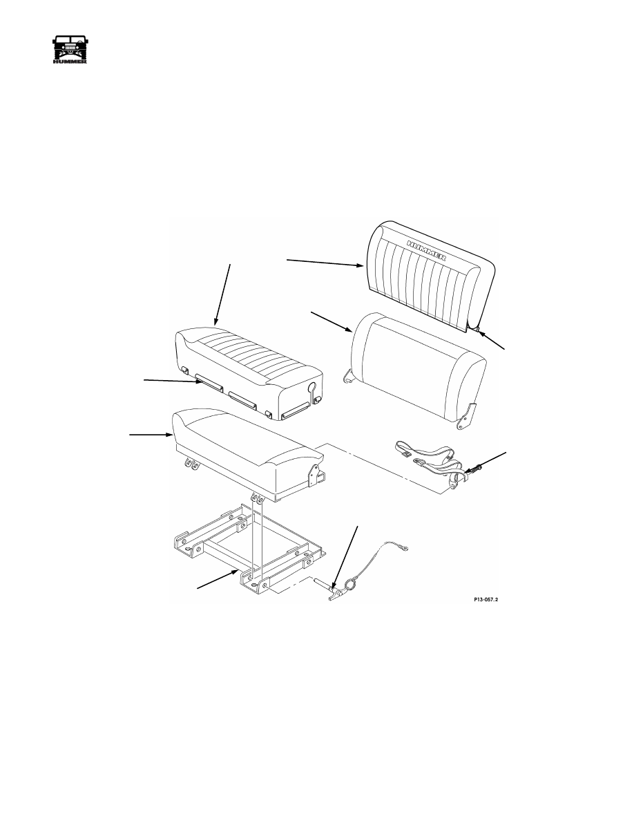
UPHOLSTERY, LEATHER AUXILIARY SEAT

Removal


1.

Remove the four locking pins securing the auxiliary seat to 
the seat frame (See Figure 13-63).

2.

Remove the auxiliary seat from the seat frame.

3.

Seat Base:

a.

Remove the bolts securing the safety belts to the rear
of the auxiliary seat cushion frame.

b.

Remove the safety belts from the auxiliary seat
cushion frame.

c.

Release the plastic “J” retainers from the seat cushion
frame and remove the fabric from the seat cushion.

4.

Seat Back:

a.

Release the hook and loop securing the front portion
of the fabric to the rear fabric at the bottom of the seat
back.

b.

Pull the fabric upward and remove it from the seat
back.


Figure 13-63:   Auxiliary Seat Cover Installation.


Installation


1.

Seat Base:

a.

Using the original fabric as a template, mark and cut
the leather seat cushion upholstery for the safety belt
mounting hardware.

b.

Position the leather on the seat cushion and secure the
plastic “J” retainers to the seat cushion frame.

c.

Install the safety belts through the leather upholstery
into the seat frame and torque the fasteners to 72-78
lb-ft (98-106 N•m).

2.

Seat Back:

a.

Slide the leather upholstery down onto the seat back
and secure the hook and loop at the bottom of the seat
back.

3.

Install the auxiliary seat on the seat frame and secure with
the four locking pins.


CAUTION: 


Locking pins must be fully inserted into the seat

frame. The balls near the end of the pins must be visible at the
inboard side of the seat frame bracket.

SEAT

BACK

SEAT

CUSHION

SAFETY

BELT

SEAT

FRAME

LOCKING

PIN

PLASTIC

“J” RETAINER

HOOK

LEATHER

UPHOLSTERY

AND LOOP


13-30

Accessories


_____________________________________________________________


®


HOURMETER


By tying into the fuel pump relay hot lead, the hourmeter records
engine running time. This is especially useful in fleet applications
where vehicles experience extensive idling. The electrical connector
is wired into the engine harness, ready for hourmeter installation. 


Removal


1.

Remove the left side cowl cover (Figure 13-64).

2.

Pull tabs on either side of spring clip while simultaneously
pulling spring clip away from mounting bracket
(Figure 13-64). 


Figure 13-64:   Hourmeter Removal


3.

Pull hourmeter out of mounting bracket far enough to
access mounting bracket bolts. 

4.

Remove bolts and washers securing mounting bracket to cowl.

5.

Follow lead from hourmeter to electrical connectors and
unplug connectors  (Figure 13-65). 


Figure 13-65:   Electrical Connector Location


6.

Remove hourmeter assembly from vehicle. 


Installation


1.

Secure mounting bracket to driver side cowl with bolts and 
washers  (Figure 13-64). 

2.

Push hourmeter into mounting bracket and secure with
spring clip. 

3.

Plug engine harness connector into hourmeter connector
(Figure 13-65). 

4.

Install the cowl cover.

5.

Verify that hourmeter records engine running time. 

HOURMETER

MOUNTING

BRACKET

LEAD

SPRING

CLIP

9-P13-006

COWL

COVER

0


0 0

 0 5

 0

9-S13-004

HARNESS

CONNECTOR

HOURMETER

CONNECTOR


____________________________________________________________


 Accessories  13-31


®


05745159


OFF ROAD LIGHT PACKAGE

KC HiLites High Intensity Discharge Lighting 
System

Removal


1.

Disconnect battery ground cables.

2.

Remove switch from dash, disconnect spare power and
ground wires under dash and pull wires through cowl.

3.

Remove relay from mount point on hood lock bracket and
wire connections on power and ground studs.

4.

Loosen battery hold down bracket and slide ballast
mounting brackets out.

5.

Disconnect the wire connections upstream of each light
and remove the ballasts and related wiring.

6.

Remove lights from bumper mount brackets.


Installation


1.

Begin by mounting your HID lights to the front bumper
mount brackets on each side of the vehicle. The lights are
labeled “


driver


” and “


passenger


” which will orient the

ceramic cover on the bulb downward. Use of the front
lower hole in the bumper mount bracket should afford ample
clearance to the hood and brush guard  (Figure 13-66).
Assure the steering stops are adjusted correctly to main-
tain adequate clearance between the tires and the lights. 
Suspension deflection during off-road driving will affect
this clearance.


Figure 13-66:   Light Mounting Point


2.

The ballasts mount above the vehicle’s batteries. Loosen
the battery hold-down hardware, and slide two ballast
mounting brackets between the batteries and the battery
hold-down on the inboard side and two on the outboard
side (Figure 

13-67). The ballast marked “passenger”

mounts forward of, and close to, the center battery hold-
down stud with the long wire lead toward the front of the
vehicle. This mounting position is important to maintain
good hood-to-ballast clearance. Secure the ballasts to the
brackets with the screws and washers provided. Tighten
the battery hold-down hardware.


NOTE: 


It will be necessary to remove the closeout panel under

the left side of the dashboard to make some of the wire connec-
tions. Route wiring away from all moving components and ex-
cessive heat. Secure harnesses to the vehicle with wire ties. 


Figure 13-67:   Ballast Mounting Point

BUMPER MOUNT BRACKET

KC HILITE

BALLAST

BATTERY HOLD-DOWN
BRACKET

BALLAST

BALLAST
MOUNTING
BRACKET


13-32

Accessories


_____________________________________________________________


®


3.

Route the harness from the ballast along the passenger
side of the radiators, under the foam hood seal, to the
passenger side light. The driver side light harness routes
from the ballast across the top of the radiators, under the
foam hood seal, and down the driver side of the radiators
to the light. The harness connecting the ballasts and the
relay should be routed from the ballasts across the top of
the radiators, under the foam hood seal, to the relay mount
point


at the hood safety lock. From the relay, the power

and ground wiring connects to the power distribution studs
on the firewall and to the ground stud next to the exterior
fuse box. The blue wire routes through the ignition
interlock cable grommet in the cowl to the switch. The
white (power) and black (ground) wires connect the switch
to the orange high beam power wire near the turn signal
switch


and the instrument panel ground point under the

dash.  

4.

The red wire (Figure 13-70) containing a 30-amp in-line
fuse, supplies power to the relay on terminal 30 and
connects to the power distribution stud (+) on the firewall.
The blue wire connects terminal 86 of the relay to either of
the outside terminals on the switch. The red wire connects
terminal 87 of the relay to the ballasts. The black wire
connects terminal 85 of the relay and the ballasts to the
ground distribution stud (-)


next to the exterior fuse box.

The center (ground) terminal of the switch connects to the
instrument panel ground point under the left side of the
dash. The white wire connects the remaining outside
terminal of the switch to the orange high beam power wire
near the turn signal switch (See Figure 13-68).


Figure 13-68:   Switch Power Connection


5.

Bend the relay tab approximately 90 degrees to the relay
and mount the relay to the hood safety lock bracket with
the existing screw (Figure 13-69). Mount the relay with
the wires facing down to prevent moisture intrusion into
the relay.

6.

Mount the switch under the dash on the left side of the
steering column using the panel provided. 

a.

Use the closeout panel mount screw nearest the left
side of the steering column for the left side of the
switch panel and drill the right side switch panel
mount hole. Mark (using panel as template), center
punch and drill a 5/64” hole for mounting of the
panel.

b.

Mount the switch panel to the dash with the screws
provided. Drill a 5/16” hole in the closeout panel
forward of the switch for the wires to pass through the
closeout panel.


NOTE: 


It is easier to connect the wiring to the switch termi-

nals before snapping the switch into its hole.


Figure 13-69:   Relay Mounting Point, Hood Lock 

Bracket

Figure 13-70:   Wiring Schematic

9-S13-029

T-TAP

SWITCH

WIRE

COVER

14 GAUGE

ORANGE WIRE

T-TAP

RELAY

HOOD

SAFETY

LATCH

CTIS

COMPRESSOR

9-S13-003

7-S12-149.4

RED WIRE

RELAY

30 AMP

FUSE

86

87

85

30

BALLAST

KC HID

BALLAST

KC HID

LIGHTS

GROUND

POWER

SWITCH

BLUE WIRE

RED WIRE

BLACK WIRE

BLACK WIRE

WHITE WIRE

INSTRUMENT

PANEL

GROUND

POWER
DISTRIBUTION
STUD ON FIREWALL

GROUND STUD
AT EXTERIOR
FUSE BOX

TURN

SIGNAL

SWITCH

ORANGE WIRE

HIGH

BEAM

POWER

3 AMP

FUSE

WHITE WIRE


Content   ..  257  258  259  260   ..