Hummer H1 (2002+). Manual - part 166


  Index      Hummer     Hummer H1 - service repair manual 2002 year


Search            


Content   ..  164  165  166  167   ..


Hummer H1 (2002+). Manual - part 166


_____________________________________________________________________

 Body  10-35

®

05745159

MIRRORS

Side Mirror Replacement
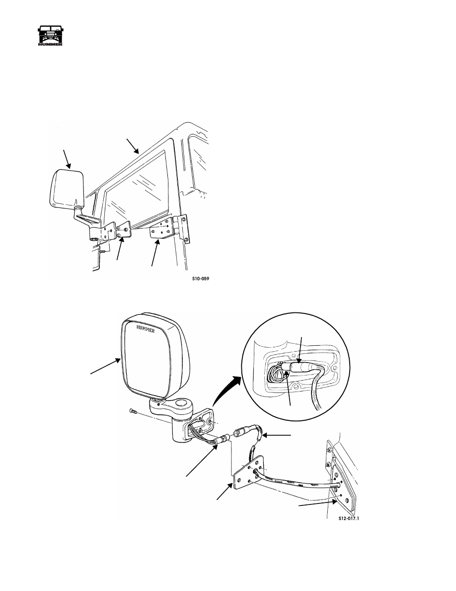
Removal 

Remove screws, mirror, and gasket from door hinge
(Figure 10-57).

Figure 10-57:   Side Mirror Assembly Replacement

Installation 

Secure gasket and mirror to door hinge with screws
(Figure 10-57).

POWER MIRRORS 

Power Mirror Assembly Replacement

Removal

1.

Remove three screws securing power mirror assembly and 
gasket to mounting plate (Figure 10-58).

2.

Disconnect power mirror assembly connector from door
jumper harness.

3.

Inspect gasket, and replace if damaged.

Installation

NOTE: 

Ensure door jumper harness is routed through gasket

before connecting to power mirror assembly.

1.

Connect power mirror assembly connector to door jumper 
harness (Figure 10-58).

NOTE: 

Wires from power mirror assembly must be coiled in

mirror housing to ensure clearance of attachments.

Figure 10-58:   Power Mirror Assembly

MIRROR

DOOR

GASKET

DOOR HINGE

POWER MIRROR 

DOOR

JUMPER
HARNESS

CONNECTOR

DOOR

JUMPER
HARNESS

MOUNTING

PLATE

GASKET

CONNECTOR

ASSEMBLY

10-36

Body

______________________________________________________________________

®

Rearview Mirror Replacement

Removal 

1.

Remove screw and rearview mirror from mirror bracket 
(Figure 10-59).

NOTE: 

Perform step 2 only if bracket requires replacement.

Mark location of bracket prior to removal.

2.

Remove bracket from windshield.

Cleaning and Inspection 

Clean epoxy remains from windshield.

Installation 

NOTE: 

Perform step 1 only if bracket was removed.

1.

Secure mirror bracket to windshield with quick-drying 
epoxy. Allow to dry (Figure 10-59).

2.

Secure rearview mirror to mirror bracket with screw.

Figure 10-59:   Rearview Mirror

DOOR REPLACEMENT

Door replacement varies in complexity depending on the type
and number of components that must be removed from the old
door and installed on the new door. Removal and installation
of these components are detailed in the previous pages of this
section. Any reference to wiring harness removal and installa-
tion is covered in Section 12. The following door replacement
procedure is written assuming the presence of power equip-
ment.

When replacing doors with manual equipment, follow this pro-
cedure but skip the power/electrical steps. Refer to manual
window regulator removal and installation at the end of this
procedure when needed.

NOTE: 

Door replacement is basically the same for all doors.

Removal

CAUTION: To avoid damage, support door during removal.

1.

Remove sideview mirror (front doors only). 

2.

Remove door harness from pillar (Section 12).

3.

Remove door stop strap assembly. 

4.

Remove twelve-point bolts and washers securing upper
door hinge to pillar (Figure 10-60).

Figure 10-60:   Door Mounting

5.

Close door.

6.

Remove twelve-point bolts and washers securing lower
door hinge to pillar and remove door.

WINDSHIELD

MIRROR BRACKET

REARVIEW MIRROR

UPPER


HINGE

PLATE

DOOR

LOWER
HINGE

PLATE

LOWER
DOOR
HINGE

PILLAR

UPPER

HINGE

 DOOR

_____________________________________________________________________

 Body  10-37

®

05745159

Disassembly 

1.

Remove twelve-point bolts, washers, and upper and lower 
hinge plates from door (Figure 10-60).

Figure 10-61:   Door Trim Breakdown

2.

Remove power windows and/or door locks switches from
door (refer to procedure in this section).

3.

Remove screws and door pull handle or armrest from door
trim panel (Figure 10-61).

4.

Remove screws securing inside door handle to door trim
panel. Pull handle away from trim panel, and disconnect
inside operating rod from handle.

5.

Remove screw/washer assemblies and door trim panel
from door.

6.

Remove vapor barrier and moisture barrier flap from door
(Figure 10-62).

7.

Disconnect inside operating rod from door latch assembly
and remove rod (Figure 10-63).

8.

Remove lock cylinder clip from lock cylinder.

9.

Push lock cylinder through outside of door. Remove clip
securing lever and lock operating rod to cylinder and
remove cylinder from door (Figure 10-65).

10. Remove nuts and lockwashers securing gasket and outside

door handle to door. Disconnect outside operating rod
from handle, and remove handle. 

Figure 10-62:   Vapor Barrier and 

Moisture Barrier Flap

11. Remove screws, lockwashers, and latch assembly from

door (Figure 10-64).

12. Remove all rods from door latch assembly.

Figure 10-63:   Inside Operating Rod Location

INSIDE

OPERATING

ROD

INSIDE DOOR

DOOR PULL

HANDLE

ARMREST

DOOR

 HANDLE

POWER

WINDOW 

SWITCH

POWER

DOOR LOCK

SWITCH

WINDOW SWITCH

(REAR DOORS)

MOISTURE

BARRIER

FLAP

VAPOR 

BARRIER

DOOR

DOOR

LOCK 

INSIDE 

OPERATING

 ROD

CYLINDER

 CLIP

 LATCH

 ASSEMBLY

LOCK 

CYLINDER

10-38

Body

______________________________________________________________________

®

Figure 10-64:   Latch Assembly

CAUTION: Firmly support glass during regulator removal to
avoid damage.

Remove power window regulator (refer to procedure in this
section).

Cleaning and Inspection 

NOTE: 

Clean all components, and examine for wear or dam-

age. Replace if necessary.

Assembly 

1.

Install power windows regulator (refer to procedure in this 
section).

2.

Install all rods on door latch assembly (Figure 10-64).

WARNING:  Screws securing latch assembly have met-
ric threads. Substituting non-metric threaded screws
can result in door opening during vehicle operation. Do
not substitute screws.

3.

Secure latch assembly to door with lockwashers and
screws.

4.

Connect outside operating rod to outside door handle, and
secure gasket and outside door handle to door with nuts
and lockwashers (Figure 10-65).

5.

(Front doors only)


Install lock cylinder in door and secure

lock operating rod and lever to lock cylinder with clip.

6.

(Front doors only) Secure lock cylinder in door with lock
cylinder clip (Figure 10-63).

7.

Install inside operating rod on door latch assembly.

Figure 10-65:   Lock Cylinder and 

Outside Door Handle

NOTE: 

Vapor barrier must be completely sealed at all edges to

prevent water entry into the interior of the vehicle.

8.

Install moisture barrier flap and vapor barrier on door
(Figure 10-62).

9.

Secure door trim panel to door with screw/washer
assemblies (Figure 10-61).

10. Connect inside operating rod to inside door handle, and

install inside door handle on door trim panel with screws.

11. Install door pull handle or armrest on door trim panel with

screws.

12. Install power window switch.

13. Secure upper and lower hinge plates to door with washers

and twelve-point screws (Figure 10-66).

Installation 

CAUTION:  To avoid damage, support door during installa-
tion.

1.

Secure lower door hinge to pillar with washers and twelve-
point screws. Do not tighten screws (Figure 10-66).

2.

Secure upper door hinge to pillar with washers and
twelve-point screws. Do not tighten screws.

3.

Install door stop strap assembly. 

4.

Install power windows and door locks harness on pillar
(Section 12).

5.

Install sideview mirror (front doors only).

6.

Install sideview mirror (front doors only).

DOOR

LATCH ASSEMBLY

OUTSIDE

DOOR

HANDLE GASKET

CLIP

LOCK

OPERATING

ROD

DOOR

LOCK

CYLINDER

OUTSIDE

OPERATING

ROD


Content   ..  164  165  166  167   ..