содержание .. 510 511 512 513 514 ..
Geely EC718, EC718RV, EC715, EC715RV. Manual part - 513
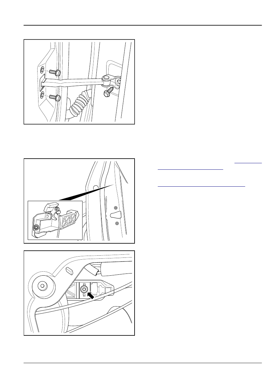
Installation Procedure:
FE12-0172b
1.
Install and tighten the front check link retaining bolts (M6).
Torque: 10 Nm (Metric) 7.4 lb-ft (US English)
2.
Tighten the retaining bolt (M8).
Torque: 25 Nm (Metric) 18.5 lb-ft (US English)
3.
Install the front door trim panel.
12.5.2.3
Front
Door
Outside
Handle
Replacement
Removal Procedure:
FE12-0173b
1.
Remove the front door trim panel. Refer to
Side Door Trim Panel Replacement
2.
Remove the front door lock cylinder. Refer to
Front Door Lock Cylinder Replacement
.
3.
Disconnect the front door outside handle rod.
4.
Remove the front door outside handle.
Note
Do not discard the seal gasket.
FE12-0174b
5.
Loosen the front door outside handle retaining blot.
6.
Remove the inner part of the front door outside handle.
Body, Sheet Metal and Painting
Doors
12-41