Geely EC718, EC718RV, EC715, EC715RV. Manual part - 319


  Главная      Geely     Geely Emgrand EC718, EC718RV, EC715, EC715RV. Workshop Manual year 2009


поиск по сайту            


содержание   ..   314  315  316  317  318  319  320  ..


Geely EC718, EC718RV, EC715, EC715RV. Manual part - 319


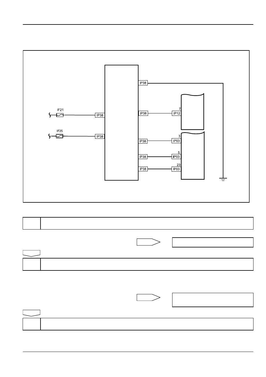
6.7.6.4 Tire Pressure Monitoring System (TPMS) Indicator Always On

Schematic:

8

7

16

5

13

14

15

TPMS

Datalink 

Connector

Instrument 

Cluster

FE06-5802b

Diagnostic Steps:

Step 1

1. Use scan tool to access the TPMS control.

(a)

Check the DTC.

Yes

Repair according to the DTC.

No

Step 2

Check the battery voltage.

(a)

Measure the battery voltage with a multimeter.
Standard Voltage: 12-14 V

Is the voltage specified value?

No

Check and replace the battery or the charging
system.

Yes

Step 3

Check TPMS control unit power supply.

Brake System

TPMS

6-109

1
9

2

10

3 4

12

5

13

6

14

7

15

8

16

TPMS Control Module Harness Connector IP38

FE06-5803b

(a)

Disconnect the battery negative cable. Refer to

2.11.8.1


Battery Disconnection

.

(b)

Disconnect TPMS control unit harness connector.

(c)

Connect the battery negative cable.

(d)

Measure voltage between TPMS control unit harness
connector IP38 terminal 8 and the body ground with a
multimeter.
Standard Voltage: 12-14 V

Is the voltage specified value?

No

Check the fuses, repair or replace the wiring
harness.

Yes

Step 4

Check TPMS control unit ground.

1
9

2

10

3 4

12

5

13

6

14

7

15

8

16

TPMS Control Module Harness Connector IP38

FE06-5804b

(a)

Measure resistance between IP38 terminal 16 and the body
ground with a multimeter.
Standard Resistance: Less than 1 Ω

Is the resistance specified value?

No

Repair or Replace the wiring harness.

Yes

Step 5

Check TPMS control unit ignition switch signal.

1
9

2

10

3 4

12

5

13

6

14

7

15

8

16

TPMS Control Module Harness Connector IP38

FE06-5805b

(a)

Turn the ignition switch to the ON position.

(b)

Measure voltage between connector IP38 terminal 7 and the
body ground with a multimeter.
Standard Voltage: 12-14 V

Is the voltage specified value?
Note: The circuit does not provide TPMS receiver unit working
current, it is only used as a logic level input.

No

Check the fuses, repair or replace the wiring
harness.

6-110

TPMS

Brake System

Yes

Step 6

Replace the TPMS control unit.

(a)

Disconnect the battery negative cable. Refer to

2.11.8.1


Battery Disconnection

.

(b)

Replace the TPMS control unit. Refer to 

6.7.7.1


TPMS

Control Unit Replacement

.

(c)

Confirm that the repair is completed.

Next

Step 7

System normal.

Brake System

TPMS

6-111

6.7.7 Removal and Installation
6.7.7.1 TPMS Control Unit Replacement

Removal Procedure:

Warning!

Refer to "Battery Disconnect Warning" in "Warnings and
Notices" .

FE06-0117b

1.

Disconnect  the  battery  negative  cable.  Refer  to

2.11.8.1


Battery Disconnection

.

2.

Remove the center console. Refer to 

3.3.8.9


Shift Lever

Replacement

.

3.

Disconnect TPMS control unit wiring harness connector.

4.

Remove the TPMS control unit retaining bolts.

Installation Procedure:

FE06-0118b

1.

Install the TPMS control unit retaining bolts.

Torque: 9 Nm (Metric) 6.7 lb-ft (US English)

2.

Connect TPMS control unit wiring harness connector.

3.

Install the center console.

4.

Connect the battery negative cable.

6.7.7.2 TPMS Sensor Replacement

Removal Procedure:

Warning!

Refer to "Battery Disconnect Warning" in "Warnings and
Notices" .

6-112

TPMS

Brake System


содержание   ..   314  315  316  317  318  319  320  ..