содержание .. 194 195 196 197 198 199 ..
Geely EC718, EC718RV, EC715, EC715RV. Manual part - 198
FE02-5263b
2
1
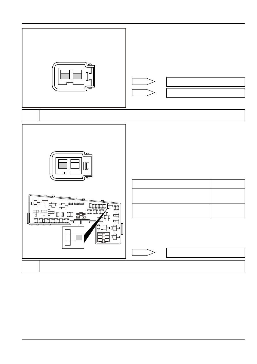
Cylinder No.3 Fuel Injector Harness
Connector EO13
(a)
Turn the ignition switch to "OFF" position.
(b)
Disconnect cylinder No.3 fuel injector wiring harness
connector EO13.
(c)
Connect a light-emitting diodes test lamp to the fuel injector
wiring harness connector EO13 terminal No.1 and 2.
(d)
Start the engine.
(e)
Observe whether test lamp is flashing.
Is the test lamp flashing?
No
Yes
Step 5
Check and repair cylinder No.3 fuel injector power circuit.
1413 12 1110
5
1
2
3
4
6
7
8
9
J
L
K
I
G
D
C
B
E
F
A
86
86
30
87
85
86
86
87
87
87
30
30
30
85
85
85
2
2
3
3
5
5
1
1
1
2
5 3
1
2
5 3
86
87
30
1
1
2
5
3
2
5
3
85
EF14
EF24
EF28
EF27
EF26
EF18
EF07
EF06
EF30
EF19
EF20
EF21
EF22
EF23
EF25
EF15
EF16
EF17
EF13
EF12
EF1
1
EF10
EF09
EF08
EF05
EF04
EF03
EF02
EF01
G
1
2
5 3
2
1
Cylinder No.3 Fuel Injector Harness
Connector EO13
FE02-5264b
(a)
Turn the ignition switch to "OFF" position.
(b)
Disconnect the fuel injector wiring harness connector EO13.
(c)
Remove the engine main relay.
(d)
Measure resistance between cylinder No.3 fuel injector
wiring harness connector EO13 terminal No.2 and engine
main relay terminal No.3.
(e)
Measure resistance between cylinder No.3 fuel injector
wiring harness connector EO13 terminal No.2 and a reliable
ground.
Test Items
Standard Value
Resistance Between EO13 (2) and Main
Relay Terminal No.3
Less than 1 Ω
Resistance Between EO13 (2) and A
Reliable Ground
10 kΩ or higher
(f)
Install the engine main relay.
(g)
Connect cylinder No.3 fuel injector wiring harness connector
EO13.
Exclude fuel injector power circuit malfunction.
Next
Step 6
Check cylinder No.3 fuel injector control circuit.
Engine
Control System JL4G15-D
2-707