содержание .. 192 193 194 195 196 ..
Geely EC718, EC718RV, EC715, EC715RV. Manual part - 195
2. Conditions For Setting DTC and The Fault Location:
DTC Code
DTC Detection Strategy
Conditions For Setting The DTC (Control
Strategy)
Fault Locations
P0230
Hardware Circuit Checks
The ignition switch is turned on, turning on
time longer than the system preset
threshold. the fuel pump relay voltage is
too high or too low.
1. Relay Circuit
2. Relay
3. ECM
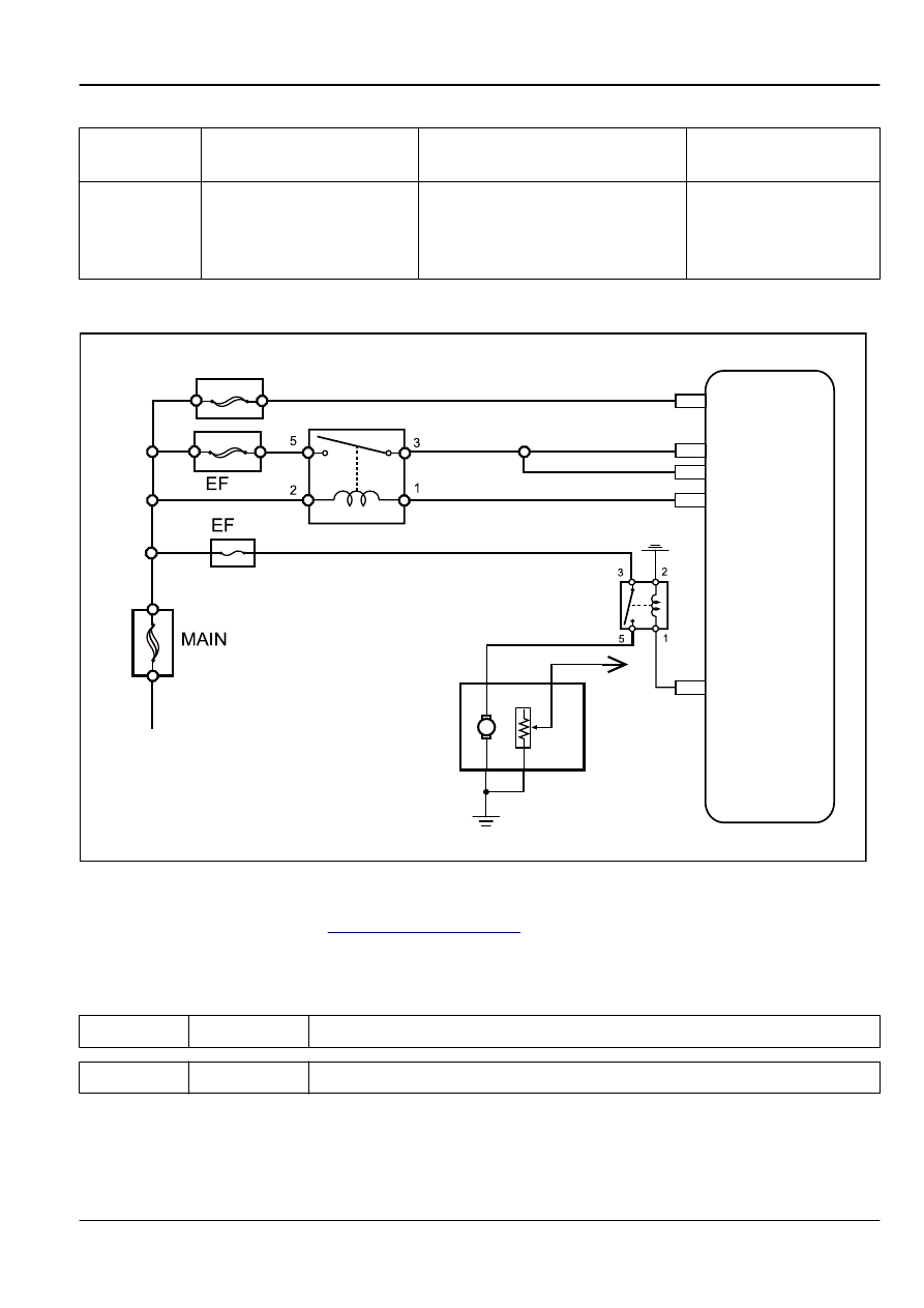
3. Schematic
05
12
EO35
EO35
EO35
EO35
EO35
2
4
3
1
M
71
FPR
62
MPR
VBATPROT
VBATPROT
22
6
VBAT
1
EF04
Main Relay
From Battery
Fuel Pump Unit
To
Instrument
Cluster
Engine
Control
Module
Fuel Pump Relay
FE02-5250b
4. Diagnostic Steps:
For fuel pump relay diagnostic. Refer to
2.12.7.29 DTC P0261 P0262
1. DTC Descriptor:
DTC
P0261
Cylinder No.1 Fuel Injector Circuit Low Voltage Fault
DTC
P0262
Cylinder No.1 Fuel Injector Circuit High Voltage Fault
Engine
Control System JL4G15-D
2-695