содержание .. 194 195 196 197 198 199 200 ..
Geely EC718, EC718RV, EC715, EC715RV. Manual part - 199
2
1
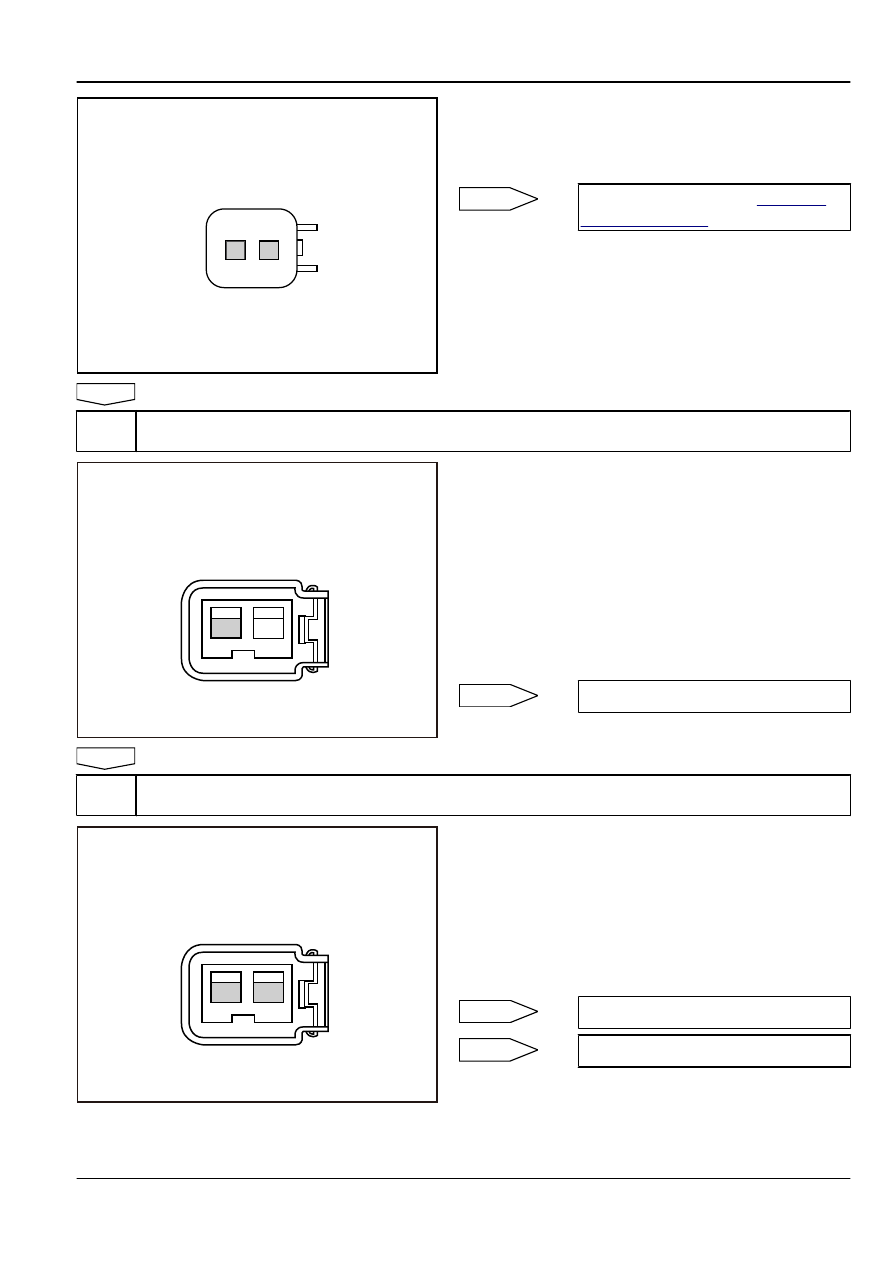
Cylinder No.4 Fuel Injector
FE02-5070b
(a)
Disconnect the fuel injector wiring harness connector EO14.
(b)
Measure resistance between the two fuel injector terminals.
Standard Resistance: 11.6-12.4 Ω at 20°C(68 ºF)
(c)
Connect the fuel injector wiring harness connector EO14.
No
replace fuel injector. Refer to
.
Yes
Step 3
Measure fuel injector working power supply.
FE02-5267b
2
1
Cylinder No.4 Fuel Injector Harness
Connector EO14
(a)
Turn the ignition switch to "OFF" position.
(b)
Disconnect cylinder No.4 fuel injector wiring harness
connector EO14.
(c)
Turn the ignition switch to "ON" position.
(d)
Measure voltage between cylinder No.4 fuel injector wiring
harness connector EO14 terminal No.2 and a reliable ground.
Standard Voltage: 11-14 V
(e)
Connect cylinder No.4 fuel injector wiring harness connector
EO14.
Voltage normal?
No
Yes
Step 4
Check the fuel injector control circuit.
FE02-5268b
2
1
Cylinder No.4 Fuel Injector Harness
Connector EO14
(a)
Turn the ignition switch to "OFF" position.
(b)
Disconnect cylinder No.4 fuel injector wiring harness
connector EO14.
(c)
Connect a light-emitting diodes test lamp to the fuel injector
wiring harness connector EO14 terminal No.1 and 2.
(d)
Start the engine.
(e)
Observe whether test lamp is flashing.
Is the test lamp flashing?
No
Yes
Engine
Control System JL4G15-D
2-711