содержание .. 30 31 32 ..
Geely FC. Manual part - 31
Driveshaft--Front drive shaft
Transmission shaft
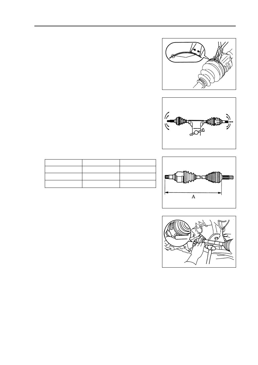
Left mm
Right mm
A type
570.2 ± 5
842.7 ± 5
B type
570.2 ± 5
847.3 ± 5
C type
570.2 ± 5
844.7 ± 5
(b) Mesh clamp type:
Liking that shown in figure, use pliers to assemble No.2
fixing clamp of inner joint dust-proof cover.
32. Check front drive shaft.
(a) Check whether there is any obvious clearance on exterior
joint.
(b) Check whether inner joint could slide smoothly in pushing
direction.
(c) Check whether there is any obvious clearance of inner joint
in radial direction.
(d) Check whether the dustproof cover is damaged.
Note: drive shaft assembly should keep moving on hori-
zontal position.
33. Assemble left front drive shaft assembly [64000082]
(a) Spread ATF on gear slot of inner joint shaft assembly.
(b) Put gear slot of drive shaft in integrated transmission, then
use copper stick and hammer to knock drive shaft to its
position.
Note:
z
make the placket of clasp face the downside to
assemble.
z
Be careful not to damage the seal oil
Hint: Whether the drive shaft contacts with gear shaft
could be felt by the sound or feeling in running process.
(c) Assemble seal board of left front swing board.
34. Assemble left front shaft hub assembly.
Assemble left front drive shaft assembly to left front hub assembly.
Note:
z
Do not damage exterior joint dustproof cover.
z
Do not damage the stator of speed sensor.
Hint: A size, please referring to following table.
Pliers
clamp
121