Freightliner FLA/FLB/FLC/FLD/FLL. Manual - part 32
3.
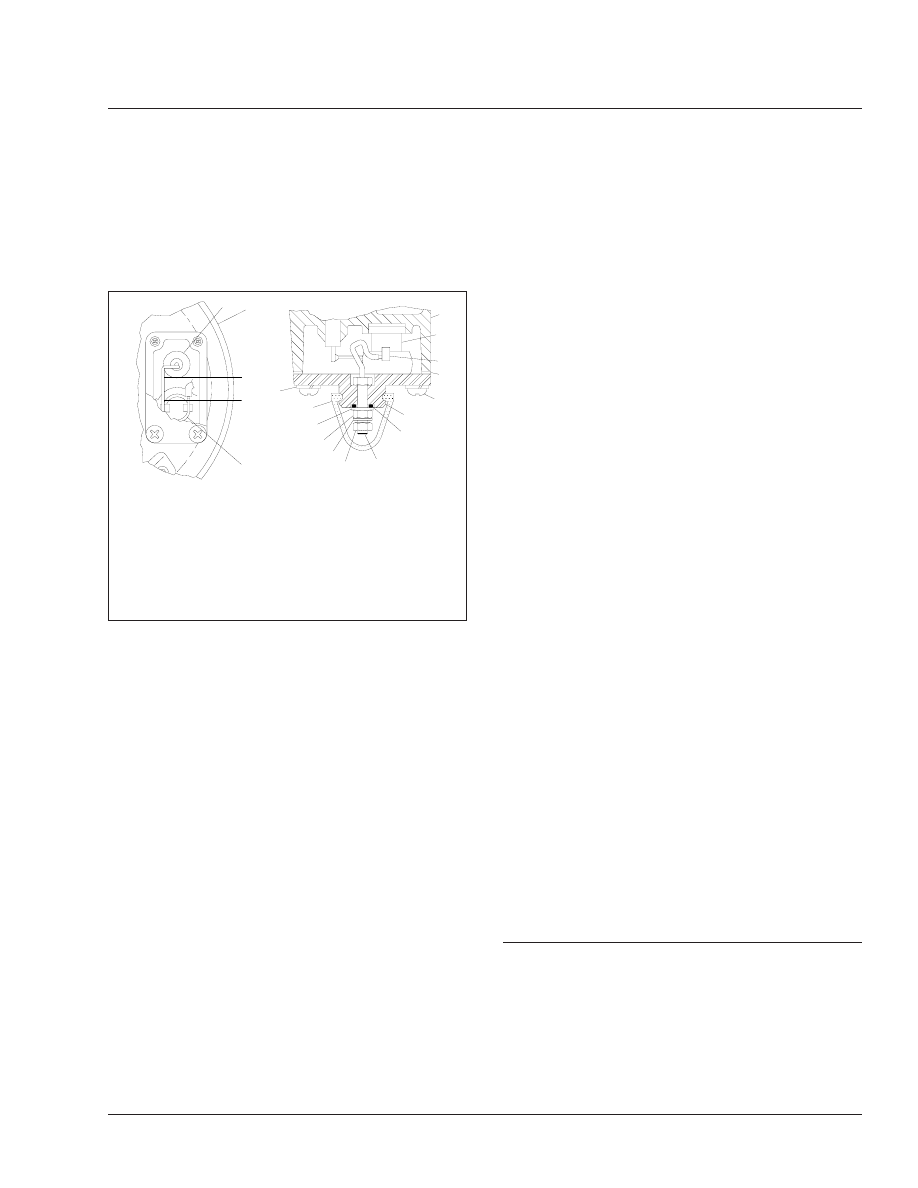
Using an ohmmeter, check resistance between
the electrical terminal and the metal end cover.
See
. Resistance should be 2.0 to 4.0
ohms for a 12-volt/60-watt end cover, and 4.0 to
7.0 ohms for a 24-volt/120-watt end cover.
4.
Warm the end cover assembly to over 90°F
(32°C) and check resistance as above. Resis-
tance should exceed 1000 ohms.
If resistance values are within stated limits, the
thermostat and heater are operating properly. If
resistance values are outside stated limits, pro-
ceed to the next step to determine the cause.
5.
With the ignition or engine control switch off, re-
move the thermostat cover. See
. Using an
ohmmeter, check resistance between the metal
end cover and the heater post. For a 12-volt/60-
watt end cover, resistance should be 2.0 to 2.8
ohms, and for a 24-volt/120-watt end cover, re-
sistance should be 4.0 to 4.6 ohms. If the heater
resistance is outside stated limits, install a new
or remanufactured end cover.
6.
Check that a good ground path exists between
the air dryer end cover casting and the vehicle
chassis. Correct if needed.
If the heater resistance is within stated limits, the
thermostat is defective. Replace the thermostat
(kit number 102657) or install a new or remanu-
factured end cover.
7.
Install the thermostat cover (Ref. 10) as shown in
; be sure the rubber spacer and gasket are
correctly installed.
Bendix AD–9
During cold weather, check operation of the end
cover heater-and-thermostat assembly.
1.
With the ignition on, check for voltage to the
heater-and-thermostat assembly. Unplug the
electrical connector at the air dryer, and place a
test lead on each pin of the male connector. If
there is no voltage, look for a blown fuse, broken
wires, or corrosion in the vehicle wiring harness.
Check that a good ground path exists.
2.
Check thermostat and heater operation. Turn off
the ignition switch and cool the end cover as-
sembly to below 40°F (4°C). Using an ohmmeter,
check resistance between the electrical pins in
the female connector. Resistance should be 1.5
to 3.0 ohms for the 12-volt heater, and 6.8 to 9.0
ohms for the 24-volt heater. Some early models
of the AD–9 will have resistance readings of 1.0
to 2.5 ohms for the 12-volt heater, and 4.8 to 7.2
ohms for the 24-volt heater. If resistance is
higher than this, replace the purge-valve housing
assembly, which includes the heater-and-
thermostat assembly.
3.
Warm the end cover assembly to over 90°F
(32°C) and again check resistance. It should ex-
ceed 1000 ohms. If it does, the thermostat-and-
heater assembly is operating properly. If it
doesn’t, replace the purge-valve housing assem-
bly, which includes the heater-and-thermostat
assembly.
42–11 Bendix Air Dryer or
Anchorlok Aftercooler
Inspecting (Bendix
AD–2, AD–4, AD–9, or
Anchorlok)
Bendix AD–2, AD–4, or AD–9
Check reservoirs for moisture. A small amount (tea-
spoon or less) is normal. An excess may indicate
that desiccant replacement is necessary.
8
8
5
4
7
6
3
3
10
9
11
12
13
1
2
3
f420016a
2
10/11/94
A
B
1.
Heater Post
2.
Air Dryer End Cover
3.
Thermostat/Terminal
Assembly
4.
Lockwasher
5.
Boot
6.
Washer
7.
Lockwasher
8.
Nut
9.
O-Ring
10. Thermostat Cover
11. Screw
12. Thermostat Cover
Gasket
13. Spacer
Fig. 9, Air Dryer Thermostat Assembly
Brakes
42
42/9