Freightliner Cascadia. Manual - part 32


  Index      Freightliner     Freightliner Cascadia - service manual


Search            


Content   ..  30  31  32  33   ..


Freightliner Cascadia. Manual - part 32


f490283

1

2

2

5

6

5

7

8

9

3

3

4

10/20/2006

A

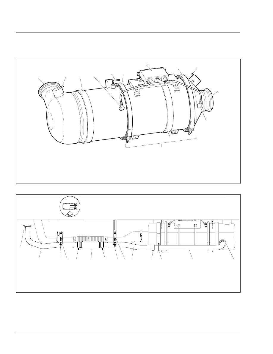
A. Inspect this area of the canister for dents.
1.

Marmon Fitting at Inlet from Turbocharger

2.

DOC Temperature Sensor

3.

ATD Mounting Band

4.

DPF Intake Pressure Sensor

5.

DPF V-Band Mounting Clamps

6.

Sensor Housing

7.

DPF Outlet Temperature Sensor

8.

Exhaust Outlet Marmon Fitting

9.

DPF Outlet Pressure Sensor

Fig. 4, Typical EPA07 Aftertreatment Device

02/24/2011

f490456

1

1

2

3

4

5

6

5

3

7

8

9

3

10

1.

Clamp

2.

Inlet Pipe

3.

U-Clamp

4.

Forward Pipe-Support Brace

5.

Slip Clamp

6.

CGI Bellows

7.

Center Pipe-Support Brace

8.

Center Pipe

9.

Clamp

10. Outlet Pipe

Fig. 5, CAT EPA07 Exhaust Installation with CGI Bellows

Exhaust

49

49/6

49–02 CAT CGI Bellows

Replacement

On vehicles with CAT EPA07 compliant engines, re-
place the CGI bellows at the M3 maintenance inter-
val to prevent a later failure.

NOTICE

A leak in the CGI piping, including the bellows,
will allow unfiltered air and contaminants into the
engine intake, and can cause serious engine
damage.

1.

Park the vehicle, set the parking brake, chock
the wheels.

2.

Open the hood.

3.

Remove the right side inner fender/splash shield
as needed.

4.

Remove the CGI piping between the engine and
aftertreatment device (ATD).

See

Fig. 5

.

5.

On the workbench, remove the CGI bellows from
the exhaust piping. Do not damage the piping.

NOTE: The following step, and its substeps, is
to be done without the bellows installed. This
will align the pipes so that the bellows can be
installed correctly.

6.

Install the CGI piping (without CGI bellows) and
align piping.

6.1

Attach the aft CGI pipe to the ATD.

6.2

Attach the forward CGI pipe to the en-
gine.

f490024a

1

2

3

06/01/93

4

1.

Flex Hose

2.

V-Band Coupling

3.

Exhaust Pipe

4.

Turbocharger Exhaust
Outlet

Fig. 6, V-Band Coupling and Flex Hose

08/25/95

f490127

1

2

3

1.

Exhaust Pipe

2.

Exhaust Elbow Isolator

3.

Mounting Nut

Fig. 7, Exhaust Elbow Isolator

f490025a

05/28/93

Fig. 8, Donaldson Sealclamp Wide-Band Exhaust

Clamp

Exhaust

49

49/7

NOTICE

When the CGI pipes and bellows are installed,
there should be approximately 3/4 inch (19 mm)
clearance from the main bellows. Contact between
the bellows could result in an exhaust leak, which
in this case may allow ingestion of contaminants
into the engine causing engine damage.

6.3

Use a straightedge to align the pipes so
that the pipe ends that attach to the bel-
lows are parallel and concentric.

NOTICE

When shortening the CGI pipe(s), it is critical to
leave a minimum of 1 inch (25.4 mm) of straight
pipe on the end of each CGI pipe to allow for pipe
insertion and clamp clearance. Failure to do this
could result in an exhaust leak, which in this case
may allow ingestion of contaminants into the en-
gine causing engine damage.

7.

Once the pipes are aligned, measure the pipe
gap between the CGI pipes and record the dis-
tance. See

Fig. 9

Ref. A.

The existing pipe gap is designed at 10 inches
(254 mm). A 10.75 inches (273 mm) pipe gap is
required for the replacement CGI bellows and
clamps. This requires one or both of the CGI
pipes to be shortened.

8.

Using a yellow paint pen, mark the pipes 1.5
inches (38 mm) in from the end of each pipe.
These two marks will be used to center the bel-
lows between the two pipes.

9.

Once the pipes are correctly aligned and sepa-
rated at the correct distance, secure the aft CGI
pipe to the ATD and to any CGI pipe support
brackets.

10. Remove the forward CGI pipe from the truck.

11. Slide the slip clamp, with the retaining ring and

graphite gasket ring, on the aft CGI pipe. See

Fig. 10

for proper installation.

12. Slide the new bellows onto the aft CGI pipe as

far as it will go. See

Fig. 11

Ref. A. Measure-

ment A should be at least 7/16 inch (10 mm)
past the face of the flange.

02/23/2011

f490457

1

2

A

A. Measure the pipe gap.
1.

CGI Aft Pipe

2.

CGI Forward Pipe

Fig. 9, Measuring the Pipe Gap (typical)

01/29/2010

1

2

3

4

5

f490415

1.

Aft CGI Pipe

2.

Retaining Ring

3.

Graphite Gasket

4.

Slip Clamp

5.

CGI Bellows

Fig. 10, Aft Facing Slip Clamp Installation

02/23/2011

f490458

A

A

2

1

3

A. At least 7/16 inch (10 mm)
1.

Forward CGI Pipe

2.

CGI Bellows

3.

Aft CGI Pipe

Fig. 11, CGI Bellows Installation

Exhaust

49

49/8

13. Install the slip clamp with the retaining ring and

graphite gasket ring onto the forward CGI pipe.
See

Fig. 12

for proper installation.

14. Slide the end of the forward CGI pipe into the

bellows, and properly align the pipe.

15. Secure the forward CGI pipe to the engine and

any CGI pipe support brackets.

16. Using the yellow marks, center the bellows be-

tween the exhaust pipes. Verify that the pipe is
inserted at least 7/16 inch (10 mm) past the face
of the flange. See

Fig. 11

Ref. A.

17. Install the slip clamps on the bellows. Tighten the

slip clamps 11 lbf·ft (15 N·m).

18. Start the engine and check for exhaust leaks.

Tighten any clamps as needed.

02/08/2010

f490417

5

4

3

2

1

1.

CGI Bellows

2.

Slip Clamp

3.

Retaining Ring

4.

Graphite Gasket

5.

Forward CGI Pipe

Fig. 12, Forward Facing Slip Clamp Installation

Exhaust

49

49/9


Content   ..  30  31  32  33   ..