Freightliner Business Class. Manual - part 31
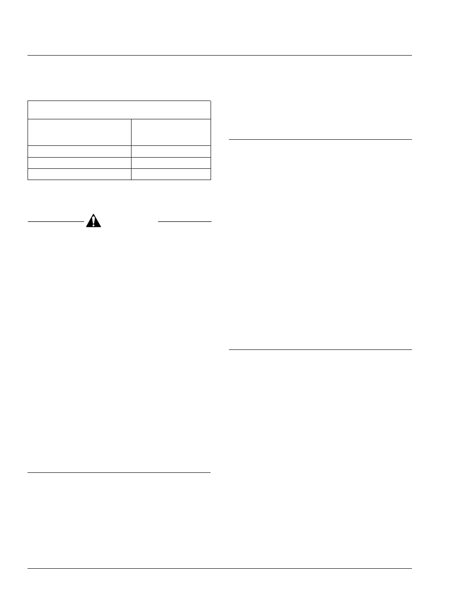
Maximum Allowable Brake Chamber Stroke, with
Meritor Automatic Slack Adjusters
Chamber Size Effective Area:
square inches
Maximum Allowable
Stroke:
*
inches (mm)
(B minus A)
24
Less than 1-3/4 (44)
24 (long stroke)
Less than 2 (51)
30
Less than 2 (51)
*
Adjust the brakes whenever the applied stroke exceeds the maximum.
Table 4, Maximum Allowable Brake Chamber Stroke,
with Meritor Automatic Slack Adjusters
CAUTION
Before turning the adjusting nut, remove the
pressure-relief capscrew, gasket, pawl spring, and
pawl. If equipped with a pull-pawl assembly, raise
the relief cap as instructed. Failure to do so could
strip the teeth on the pawl.
4.4
Turn the adjusting nut one-eighth turn, as
shown in
. Measure the stroke
again, and adjust until correct.
If the stroke varies or remains greater
than the specified range, check the brake
components, including the camshafts,
camshaft bushings, anchor pins, rollers,
chamber brackets, clevis, and clevis pins.
For instructions, see Group 42 of the
Business Class
®
Trucks Service Manual
.
4.5
If removed, install the pawl, pawl spring,
gasket, and pressure-relief capscrew.
Tighten the capscrew 15 to 20 lbf·ft (20 to
27 N·m). Or, remove the screwdriver from
the pull-pawl assembly (if equipped).
42–13 Automatic Slack
Adjuster Lubricating,
Meritor
Lubricate the slack adjuster using high-temperature,
water-proof grease NLGI grade 1, Texaco Thermotex
EP 1, Shell Darina No. 1, Marathon 528 heavy-duty,
Sunaplex No. 1 EP, Amdex No. 1 EP, or Philube B
No. 1. It should be smooth-textured, corrosion-
resistant grease, free of fillers and abrasives.
42–14 Automatic Slack
Adjuster Inspecting,
Meritor
1.
Remove the pressure-relief capscrew, gasket,
pawl spring, and pawl. See
, Ref. 5.
2.
Examine the pawl for grease retention and condi-
tion. If the grease is in good condition, install the
pressure-relief capscrew, gasket, pawl spring,
and pawl; then, tighten the capscrew 15 to 20
lbf·ft (20 to 27 N·m). Lube the slack adjuster
through the grease fitting until lubricant is forced
out through the pressure-relief fitting (or pawl
slot). Then, if a hollow capscrew is used, install
and tighten it 15 to 20 lbf·ft (20 to 27 N·m).
If the grease is hardened, or the pawl is dry and
shows extreme wear, remove the slack adjuster.
Disassemble and clean it. Inspect the internal
parts. Install new seals and a new boot when
assembling; then, install and lubricate the slack
adjuster. See Group 42 of the
Business Class
®
Trucks Service Manual
.
42–15 Air Dryer Checking,
Bendix AD–9
During cold-weather operation, check the operation
of the end cover heater and thermostat assembly.
1.
With the ignition on, check for voltage to the
heater and thermostat assembly. Unplug the
electrical connector at the air dryer, and place
the test leads of a voltmeter on each of the pins
of the male connector. If there is no voltage, look
for a blown fuse, broken wires, or corrosion in
the vehicle wiring harness. Check that a good
ground path exists.
2.
Check the thermostat and heater operation. Turn
off the ignition switch and cool the end cover as-
sembly to below 40°F (4°C). Using an ohmmeter,
check the resistance between the electrical pins
in the female connector. The resistance should
be 1.5 to 3.0 ohms for the 12-volt heater assem-
bly.
Warm the end cover assembly to over 90°F
(32°C) and again check the resistance. It should
exceed 1000 ohms. If it does, the thermostat and
Brakes
42
Business Class Trucks Maintenance Manual, October 1998
42/10