Freightliner Cargo Maintenance Manual - part 12
08/30/96
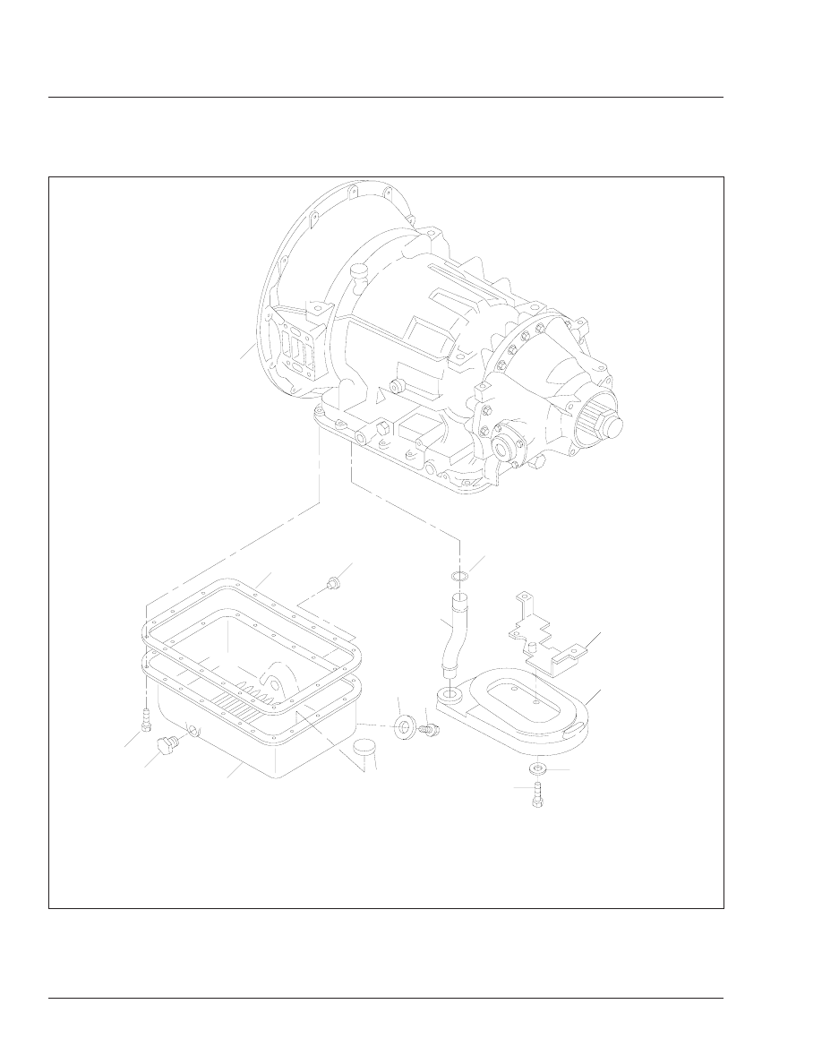
f260369
1
2
3
4
5
6
7
8
9
10
11
12
15
13
14
1.
Transmission Housing
2.
Transmission Oil Pan Gasket
3.
5/16–18 Washer-Head
Capscrew
4.
Plug
5.
Transmission Oil Pan
6.
Magnet
7.
Drain Plug Gasket
8.
Drain Plug
9.
5/16–18 x 5/8 Capscrew
10. Flatwasher
11. Transmission Oil Filter
12. Oil-Filter Spacer
13. O-Ring
14. Oil-Filter Tube
15. Plug
Fig. 9, Allison MT Series Transmission, Filter Removal
Transmission
26
Cargo Maintenance Manual, January 2000
26/8