Ford Transit (2022 year). Manual in english - page 27
 

  Index      Manuals     Ford Transit (2022 year). Manual in english


Search            copyright infringement  


Content      ..     25      26      27      28     ..


Ford Transit (2022 year). Manual in english - page 27


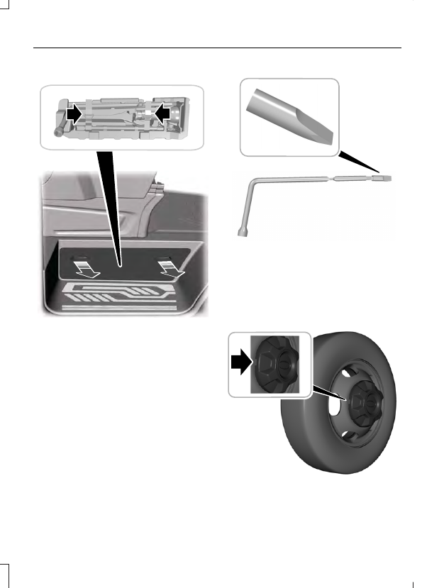
Vehicles With Dual Rear Alloy Wheels

E358085

E358088

The wheel trim removal tool is in the
storage compartment in the front
right-hand side stepwell near the lug
wrench.

Front Wheel Trim

E252525

1

1.

Locate the notch in the wheel trim.

437

Changing a Road Wheel

E358089

2

3

2. Insert the wheel trim removal tool into

the notch in the wheel trim.

3. Rotate the wheel trim removal tool and

remove the wheel trim.

Rear Wheel Trim

1

E252526

1.

Locate the notch in the wheel trim.

E358089

2

3

2. Insert the wheel trim removal tool into

the notch in the wheel trim.

3. Rotate the wheel trim removal tool and

remove the wheel trim.

Removing a Road Wheel

1.

Use the locking lug nut key to loosen
the locking lug nut.

2. Loosen the remaining lug nuts, but do

not remove them.

3. Raise your vehicle until the tire is clear

of the ground.

4. Remove the lug nuts and the road

wheel.

Note:

Do not lay alloy road wheels face

down on the ground.

Installing a Road Wheel

WARNING: 

Only use the spare

wheel and tire assembly provided as
original equipment with your vehicle.

438

Changing a Road Wheel

WARNING: 

Make sure there is no

grease or oil on the threads or the
surface between the wheel lugs and
nuts. This can cause the lug nuts to
loosen while driving.

WARNING: 

Make sure there is no

grease or oil on the threads or the
surface between the wheel lugs and
nuts. This can cause the lug nuts to
loosen while driving.

WARNING: 

When you install a

wheel, remove any corrosion, dirt or
foreign materials present on the
mounting surfaces of the wheel or the
surface of the wheel hub, brake drum or
brake disc that contacts the wheel. Make
sure to secure any fasteners that attach
the rotor to the hub so they do not
interfere with the mounting surfaces of
the wheel. Installing wheels without
following these steps can cause the
wheel nuts to loosen and the wheel to
come off while your vehicle is in motion,
resulting in loss of vehicle control,
personal injury or death.

WARNING: 

Have the lug nuts

checked for tightness and the tire
pressure checked as soon as possible.

1.

Install the wheel.

E70961

1

2

3

4

5

6

1

2

3

4

5

2. Install all of the lug nuts and partially

tighten them in the sequence shown.

3. Lower your vehicle and remove the

vehicle jack.

4. Fully tighten all of the lug nuts in the

sequence shown.  See 

Locating the

Tire label

 (page 411).

5. Install the wheel trim.

Note:

Make sure that the lug nuts are fully

seated against the wheel.

Note:

Alloy wheel lug nuts are suitable for

use on a steel spare wheel.

Note:

If the spare wheel is not the same

type and size as your vehicle road wheel
replace it as soon as possible.

439

Changing a Road Wheel

Note:

 Check the lug nuts for correct

tightness and check the tire pressure as
soon as possible.  See 

Locating the Tire

label

 (page 411).

E227387

Note:

When installing dual rear wheels,

align the valve stems facing each other.

Stowing the Wheel and Vehicle
Jack

Note:

 Do not raise the spare wheel bracket

without a wheel attached.  If you lower the
spare wheel bracket without a wheel
attached, you may damage the winch
mechanism.

1.

Attach the spare wheel bracket to the
wheel using the retaining nut.

2. Slide the cable through the slot and

attach the spare wheel bracket to the
winch.

3. Rotate the cable through 90 degrees

and lower the cable end cover.

E145138

4. Insert the flat end of the lug wrench

into the socket.  Turn it clockwise until
you feel a strong resistance.

Note:

Make sure the spare wheel is secure

by tightening the winch until you feel a slip.

5. Stow the vehicle jack, jack handle and

lug wrench in their correct locations
and secure them with the straps.

CHANGING A FLAT TIRE -
ELECTRIC MOTOR

WARNING: 

Failure to follow these

guidelines could result in an increased
risk of loss of vehicle control, injury or
death.

440

Changing a Road Wheel

WARNING: 

Do not attempt to

change a tire on the side of the vehicle
close to moving traffic. Pull far enough
off the road to not obstruct the flow of
traffic and avoid the danger of being hit
when operating the jack or changing the
wheel.

WARNING: 

Switch the ignition off

and apply the parking brake. If your
vehicle has a manual transmission, shift
into first or reverse gear. If your vehicle
has an automatic transmission, shift into
park (P).

WARNING: 

Make sure that your

vehicle is on firm and level ground with
the front wheels pointing straight ahead
and set up a warning triangle if available.

WARNING: 

To help prevent your

vehicle from moving when changing a
wheel, use an appropriate block or wheel
chock to secure the wheel diagonally
opposite to the wheel being changed.
For example, when changing the front
left wheel, place an appropriate block or
wheel chock on the right rear wheel.

Make sure all passengers are out of your
vehicle.

Note:

: The use of tire sealants can damage

the tire pressure monitoring system.

Note:

The tire pressure monitoring system

indicator light illuminates when the spare
tire is in use. To restore the full function of
the monitoring system, all road wheels
equipped with tire pressure monitoring
sensors must be mounted on this vehicle.

Note:

If your vehicle has a tire pressure

monitoring system, the warning indicator
flashes if you fit the spare wheel to your
vehicle. To restore the correct operation of
the tire pressure monitoring system, you
must have the repaired road wheel and tire
assembly refitted to your vehicle.  See 

Tire

Pressure Monitoring System – Warning
Lamps

 (page 429).  To prevent damage

occurring to the tire pressure monitoring
system sensors, make sure you have the
damaged tire repaired or replaced by a tire
professional.

If the spare wheel is the same type and
size as your vehicle road wheel, you can fit
the spare wheel and continue to drive in
the normal manner.

If the spare wheel is not the same type and
size as your vehicle road wheel, it has a
label showing the maximum driving speed
limit.

The spare wheel is under the front of the
vehicle on all battery electric vehicles
except E-LWB van, which is at the rear.

Locking Lug Nuts

 (If Equipped)

You can obtain replacement locking lug
nuts or a locking lug nut key using the
reference number certificate.

The locking lug nut key is located in the
glove box or in the storage compartment
in the front right-hand side stepwell.

441

Changing a Road Wheel

Van and E-LWB Van

E358082

If you have a van, find the winch on the
chassis rail in front of the right side front
wheel.

E145138

If you have E-LWB van, open the rear doors
and remove the grommet.

E358083

1.

Insert the square end of the wheel
brace or the short arm of the jack
handle into the socket. Turn
counterclockwise until the spare wheel
rests on the ground and the cable is
loose.

E146811

2. Raise the cable end cover.

442

Changing a Road Wheel

E146812

1

2

3. Rotate the cable through 90 degrees.

Slide the cable through the slot to
release the spare wheel bracket from
the winch.

E146813

4. Remove the retaining nut to release

the spare wheel bracket.

5. Leave the cable extended. You need

to use it to stow the flat wheel and tire
assembly.

Note:

 Do not raise the spare wheel bracket

without a wheel attached.  Damage to the
winch mechanism could occur.

Vehicle Jack

WARNING: 

Only use the jack

provided as original equipment with your
vehicle.

WARNING: 

The jack supplied with

this vehicle is only intended for changing
a flat tire in an emergency. Do not
attempt to do any other work on your
vehicle when it is supported by the jack,
as your vehicle could slip off the jack.
Failure to follow this instruction could
result in personal injury or death.

WARNING: 

Switch off the running

boards before jacking or placing any
object under your vehicle. Never place
your hand between the extended running
board and your vehicle. A moving running
board may cause injury.

WARNING: 

Never place anything

between the vehicle jack and your
vehicle.

WARNING: 

Never place anything

between the vehicle jack and the ground.

WARNING: 

Do not get under a

vehicle that is supported by a jack.

E166722

443

Changing a Road Wheel

Vehicle Jack Storage

E358085

The jack, jack handle and wheel brace are
in a storage compartment in the front
right-hand side stepwell.

Note:

The vehicle jack is in the load space

area on vehicles with rear climate control.

E297495

1.

Assemble the jack rod.

2. Insert the flat end of the jack rod into

the jack.

3. Insert the square end of the jack rod

into the wheel brace and rotate
clockwise to raise your vehicle.

Front Jacking Points

WARNING: 

Only use the specified

jacking points. If you use any other
locations you could damage vehicle
components, such as brake lines.

WARNING: 

Using the high voltage

battery box as a jacking point could
result in electric shock, personal injury,
fire or death.

Note:

In case of a flat tire on the front it

could be necessary to jack your vehicle to
reach the spare wheel. Withdraw the spare
wheel by holding the tread.

WARNING: 

No person should place

any portion of their body under a vehicle
that is supported by a jack.

Note:

If your vehicle has rear air

conditioning make sure the vehicle jack does
not come in contact with the air conditioning
lines.

444

Changing a Road Wheel

E357757

Position the head of the vehicle jack on the
bolted body brackets .

Rear Jacking Points Vehicles

WARNING: 

Only use the specified

jacking points. If you use any other
locations you could damage vehicle
components, such as brake lines.

WARNING: 

Using the high voltage

battery box as a jacking point could
result in electric shock, personal injury,
fire or death.

WARNING: 

No person should place

any portion of their body under a vehicle
that is supported by a jack.

E357758

Position the head of the vehicle jack under
the outer bush of the suspension arm.

445

Changing a Road Wheel

Removing a Wheel Trim

 (If Equipped)

Vehicles With Steel Wheels

E358085

The wheel trim removal tool is in the
storage compartment in the front
right-hand side stepwell near the lug
wrench.

E358088

1.

Insert the flat end of the lug wrench
between the wheel rim and the wheel
trim.

2. Carefully remove the wheel trim.

Removing a Road Wheel

1.

Use the locking lug nut key to loosen
the locking lug nut.

2. Loosen the remaining lug nuts, but do

not remove them.

3. Raise your vehicle until the tire is clear

of the ground.

4. Remove the lug nuts and the road

wheel.

Note:

Do not lay alloy road wheels face

down on the ground.

Installing a Road Wheel

WARNING: 

Only use the spare

wheel and tire assembly provided as
original equipment with your vehicle.

446

Changing a Road Wheel

WARNING: 

Make sure there is no

grease or oil on the threads or the
surface between the wheel lugs and
nuts. This can cause the lug nuts to
loosen while driving.

WARNING: 

When you install a

wheel, remove any corrosion, dirt or
foreign materials present on the
mounting surfaces of the wheel or the
surface of the wheel hub, brake drum or
brake disc that contacts the wheel. Make
sure to secure any fasteners that attach
the rotor to the hub so they do not
interfere with the mounting surfaces of
the wheel. Installing wheels without
following these steps can cause the
wheel nuts to loosen and the wheel to
come off while your vehicle is in motion,
resulting in loss of vehicle control,
personal injury or death.

WARNING: 

Have the lug nuts

checked for tightness and the tire
pressure checked as soon as possible.

1.

Install the wheel.

E70961

1

2

3

4

5

6

1

2

3

4

5

2. Install all of the lug nuts and partially

tighten them in the sequence shown.

3. Lower your vehicle and remove the

vehicle jack.

4. Fully tighten all of the lug nuts in the

sequence shown.  See 

Locating the

Tire label

 (page 411).

5. Install the wheel trim.

Note:

Make sure that the lug nuts are fully

seated against the wheel.

Note:

Alloy wheel lug nuts are suitable for

use on a steel spare wheel.

Note:

If the spare wheel is not the same

type and size as your vehicle road wheel
replace it as soon as possible.

447

Changing a Road Wheel

Note:

 Check the lug nuts for correct

tightness and check the tire pressure as
soon as possible.  See 

Locating the Tire

label

 (page 411).

Stowing the Wheel and Vehicle
Jack

Note:

 Do not raise the spare wheel bracket

without a wheel attached.  If you lower the
spare wheel bracket without a wheel
attached, you may damage the winch
mechanism.

1.

Attach the spare wheel bracket to the
wheel using the retaining nut.

2. Slide the cable through the slot and

attach the spare wheel bracket to the
winch.

3. Rotate the cable through 90 degrees

and lower the cable end cover.

4. Insert the flat end of the lug wrench

into the socket.  Turn it clockwise until
you feel a strong resistance.

Note:

Make sure the spare wheel is secure

by tightening the winch until you feel a slip.

5. Stow the vehicle jack, jack handle and

lug wrench in their correct locations
and secure them with the straps.

WHEEL NUTS

Lug Nut Torque

WARNING: 

When you install a

wheel, remove any corrosion, dirt or
foreign materials present on the
mounting surfaces of the wheel or the
surface of the wheel hub, brake drum or
brake disc that contacts the wheel. Make
sure to secure any fasteners that attach
the rotor to the hub so they do not
interfere with the mounting surfaces of

the wheel. Installing wheels without
following these steps can cause the
wheel nuts to loosen and the wheel to
come off while your vehicle is in motion,
resulting in loss of vehicle control,
personal injury or death.

WARNING: 

Only use the specific

lug nuts and wheels supplied with your
vehicle. If in doubt, contact an authorized
dealer.

WARNING: 

Do not install alloy

wheels using lug nuts designed for use
with steel wheels.

 lb.ft (Nm)

Bolt size

150 (204)

M14 x 1.5

Locking Lug Nuts

You can obtain a replacement locking lug
nut key and replacement locking lug nuts
from an authorized dealer using the
reference number certificate.

448

Changing a Road Wheel

ENGINE SPECIFICATIONS - 3.5L DURATEC

3.5L V6 TiVCT

Engine

213

Cubic inches.

Minimum 87 octane

Required fuel.

1-4-2-5-3-6

Firing order.

Coil on plug

Ignition system.

.049-.053 in. (1.25 - 1.35 mm)

Spark plug gap.

11.8:1

Compression ratio.

449

Capacities and Specifications

ENGINE SPECIFICATIONS - 3.5L ECOBOOST™

3.5L V6 EcoBoost™

Engine

213

Cubic inches.

Minimum 87 octane

Required fuel.

1-4-2-5-3-6

Firing order.

Coil on plug

Ignition system.

.030-.033 in. (.75-.85 mm)

Spark plug gap.

10.0:1

Compression ratio.

450

Capacities and Specifications

MOTORCRAFT PARTS - 3.5L DURATEC

Motorcraft Part number

Component

FA-1916

Air filter element.

FT-216

Automatic transmission fluid filter.

BXT-48H6-610

Battery - standard.

BAGM-48H6-760

Battery - alternative.

FL-500S

Oil filter.

SP-520

Spark plugs.

FP-74

Cabin air filter.

WW-2955 - driver side

Windshield wiper blades - roof med-low.

WW-2112 - passenger side

WW-2901 - driver side

Windshield wiper blades - roof low,

medium and high.

WW-2049 - passenger side

We recommend Motorcraft replacement parts available at your Ford dealer or at
fordparts.com for scheduled maintenance. These parts meet or exceed Ford Motor
Company’s specifications and are engineered for your vehicle. Use of other parts may
impact vehicle performance, emissions and durability. Your warranty may be void for any
damage related to use of other parts.

If a Motorcraft oil filter is not available, use an oil filter that meets industry performance
specification SAE/USCAR-36.

For spark plug replacement, contact an authorized dealer. Replace the spark plugs at the
appropriate intervals.  See 

Normal Scheduled Maintenance

 (page 523).

451

Capacities and Specifications

MOTORCRAFT PARTS - 3.5L ECOBOOST™

Motorcraft Part number

Component

FA-1916

Air filter element.

FT-216

Automatic transmission fluid filter.

BAGM-48H6-760

Battery.

FL-500S

Oil filter.

SP-580

Spark plugs.

FP-74

Cabin air filter.

WW-2955 - driver side

Windshield wiper blades - roof med-low.

WW-2112 - passenger side

WW-2901 - driver side

Windshield wiper blades - roof low,

medium and high.

WW-2049 - passenger side

We recommend Motorcraft replacement parts available at your Ford dealer or at
fordparts.com for scheduled maintenance. These parts meet or exceed Ford Motor
Company’s specifications and are engineered for your vehicle. Use of other parts may
impact vehicle performance, emissions and durability. Your warranty may be void for any
damage related to use of other parts.

If a Motorcraft oil filter is not available, use an oil filter that meets industry performance
specification SAE/USCAR-36.

For spark plug replacement, contact an authorized dealer. Replace the spark plugs at the
appropriate intervals.  See 

Normal Scheduled Maintenance

 (page 523).

452

Capacities and Specifications


Content      ..     25      26      27      28     ..