Ford Galaxy / Ford S-MAX. Manual - part 999


  Index      Ford     Ford Galaxy / Ford S-MAX - service repair manual 2006 year


Search            


Content   ..  997  998  999  1000   ..


Ford Galaxy / Ford S-MAX. Manual - part 999
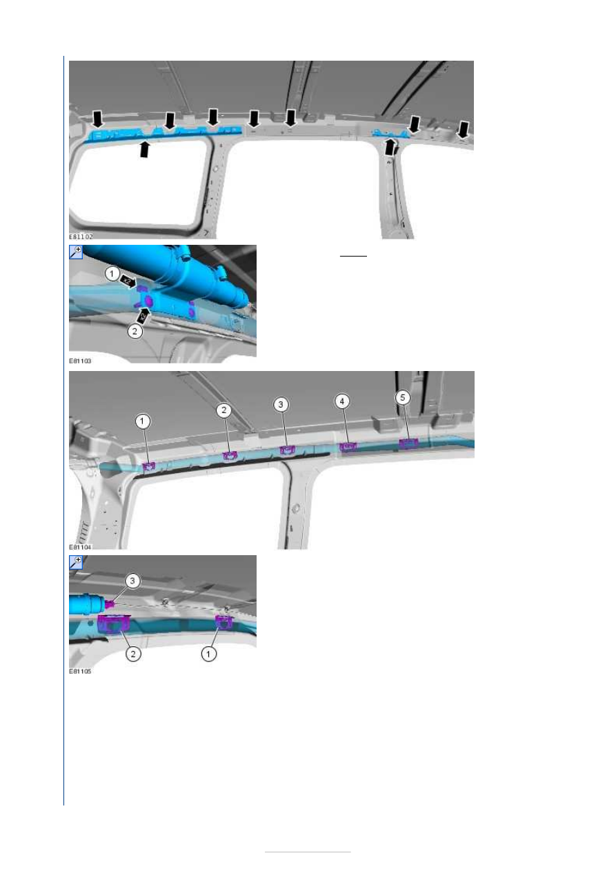


ramps for 
deformation.

2. Torque: 6 Nm 

3.

NOTE: Make 
sure that 
these 
components 
are installed 
to the noted 
removal 
position. 

Attach the side 
air bag module 
retaining clips in 
the following 
sequence. 

4.

NOTE: Make sure that these components are installed 
to the noted removal position. 

Attach the side air bag module retaining clips in the 
following sequence. 

5. This step is only required when installing the left-hand side 

air curtain. 


6. This step is only required when installing the right-hand 

side air curtain. 

7.

NOTE: Make sure that this component is installed to 
the noted removal position. 

8. Torque: 10 Nm 

9. Remove the protective strap from all of the side air bag 

module retaining clips. 

10. Install the headliner. 

11. Initialize the door window motors. 

Refer to: 

Door Window Motor Initialization

 (501-11 Glass, 

Frames and Mechanisms, General Procedures). 


Supplemental Restraint System - 
Restraints Control Module (RCM)

S-MAX/Galaxy 2006.5 (02/2006-)


Print


Removal and Installation 

General Equipment 

Removal 

WARNINGS: 

The supplemental restraint system (SRS) is active for a certain length of time after 

the power supply has been disconnected. Wait for a minimum of 3 minutes before 
disconnecting or removing any SRS components. 

Make sure that the vehicle electrical system is fully depowered and no other power 

source is connected. 

Wear safety goggles. 

Refer to: 

Supplemental Restraint System (SRS) Health and Safety Precautions

 (100-

00 General Information, Description and Operation). 

Ford diagnostic equipment

1. Disconnect the battery ground cable. 

Refer to: 

Battery Disconnect and Connect

 (414-

01 Battery, Mounting and Cables, General 
Procedures). 

2. Remove the floor console. 

Refer to: 

Floor Console - VIN Plate Body Style 

Code: M

 (501-12 Instrument Panel and Console, 

Removal and Installation). 
Refer to: 

Floor Console - Vehicles With: 

Electronic Parking Brake (EPB), VIN Plate Body 
Style Code: M

 (501-12 Instrument Panel and 

Console, Removal and Installation). 
Refer to: 

Floor Console - VIN Plate Body Style 

Code: S

 (501-12 Instrument Panel and Console, 

Removal and Installation). 
Refer to: 

Floor Console - Vehicles With: 

Electronic Parking Brake (EPB), VIN Plate Body 
Style Code: S

 (501-12 Instrument Panel and 

Console, Removal and Installation). 
Refer to: 

Floor Console Upper Section - Vehicles 

With: Center Armrest/Manually Adjusted Parking 
Brake

 (501-12 Instrument Panel and Console, 

Removal and Installation). 
Refer to: 

Floor Console Upper Section - Vehicles 

With: Manually Adjusted Parking Brake, Vehicles 
Without: Center Armrest

 (501-12 Instrument 

Panel and Console, Removal and Installation). 

3. If equipped. 

Installation 

4.  

1. Torque: 8 Nm 

2. To install, reverse the removal procedure. 

3. When a new RCM is installed, configure the RCM 

using the diagnostic tool. 

General Equipment: 

Ford diagnostic equipment


Content   ..  997  998  999  1000   ..