Ford Galaxy / Ford S-MAX. Manual - part 1000


  Index      Ford     Ford Galaxy / Ford S-MAX - service repair manual 2006 year


Search            


Content   ..  998  999  1000  1001   ..


Ford Galaxy / Ford S-MAX. Manual - part 1000


Supplemental Restraint System - 
Passenger Air Bag Deactivation (PAD) 
Switch

S-MAX/Galaxy 2006.5 (02/2006-)


Print


Removal and Installation 

Removal 

WARNINGS: 

The supplemental restraint system (SRS) is active for a certain length of time after 

the power supply has been disconnected. Wait for a minimum of 3 minutes before 
disconnecting or removing any SRS components. 

Make sure that the vehicle electrical system is fully depowered and no other power 

source is connected. 

Wear safety goggles. 

Refer to: 

Supplemental Restraint System (SRS) Health and Safety Precautions

 (100-

00 General Information, Description and Operation). 
NOTE: Removal steps in this procedure may contain installation details. 

Vehicles with air conditioning 

1. Disconnect the battery ground cable. 

Refer to: 

Battery Disconnect and Connect

 (414-

01 Battery, Mounting and Cables, General 
Procedures). 

2. Remove the navigation system digital versatile 

disc (DVD) unit, if equipped. 

Refer to: Navigation System Digital Versatile Disc 
(DVD) Unit (415-01 Information and 
Entertainment System, Removal and 
Installation). 

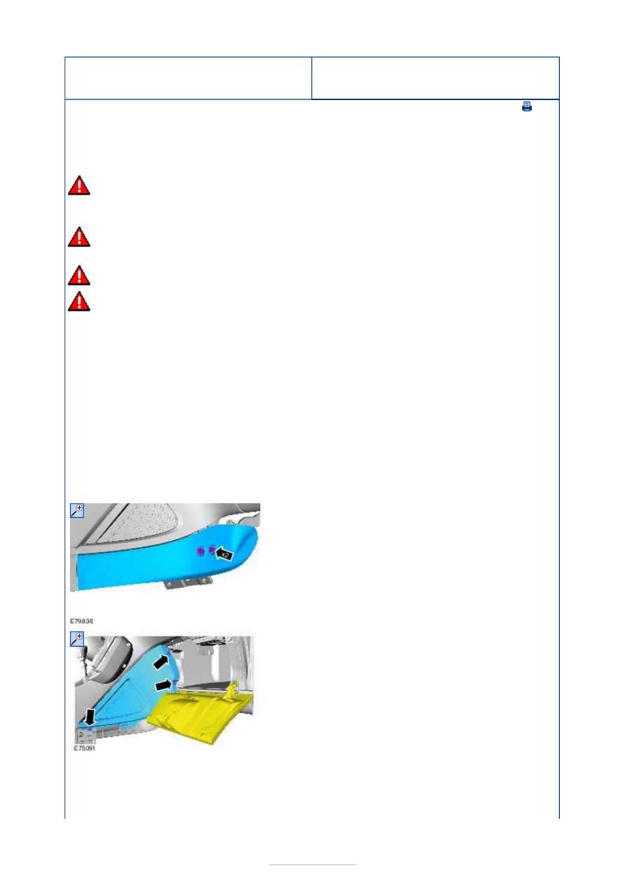
3.  

4.  

5.  


All vehicles 

Installation 

6.  

7.  

1. To install, reverse the removal procedure. 

2. Initialize the door window motors. 

Refer to: Door Window Motor Initialization (501-
11 Glass, Frames and Mechanisms, General 
Procedures). 


Supplemental Restraint System - 
Clockspring

S-MAX/Galaxy 2006.5 (02/2006-)


Print


Removal and Installation 

Removal 

Installation 

1. Refer to: 

Steering Wheel

 (211-04 Steering 

Column, Removal and Installation). 

2.  

3.  

4.   

1.

CAUTION: Make sure that the 

clockspring rotor does not rotate. 
NOTE: This step is not necessary when 
installing a new component. 

Secure the clockspring rotor with adhesive 
tape to the clockspring outer. 

5.

CAUTIONS: 

Make sure that the clockspring pins are 

not bent or damaged. 

Make sure that the clockspring rotor 

does not rotate. 

1.

CAUTIONS: 

Make sure that the clockspring pins are 

not bent or damaged. 

Make sure that the clockspring rotor 


does not rotate. 

2.

NOTE: This step is only necessary when 
installing a new component. 

3.

CAUTION: Make sure that the 

clockspring pins are not bent or damaged. 
NOTE: This step is not necessary when 
installing a new component. 

Carry out the clockspring adjustment procedure, 
if the yellow roller is not visible in the clockspring 
window. 

Refer to: 

Clockspring Adjustment

 (501-20B 

Supplemental Restraint System, General 
Procedures). 

4. To install, reverse the removal procedure. 


Content   ..  998  999  1000  1001   ..