Ford Galaxy / Ford S-MAX. Manual - part 930
 

  Index      Ford     Ford Galaxy / Ford S-MAX - service repair manual 2006 year


Search            


Content   ..  928  929  930  931   ..


Ford Galaxy / Ford S-MAX. Manual - part 930


Installation 

1.

NOTE: Minimum 1 mm bead thickness. 
NOTE: Make sure that the mating faces are clean and free of 
foreign material. 

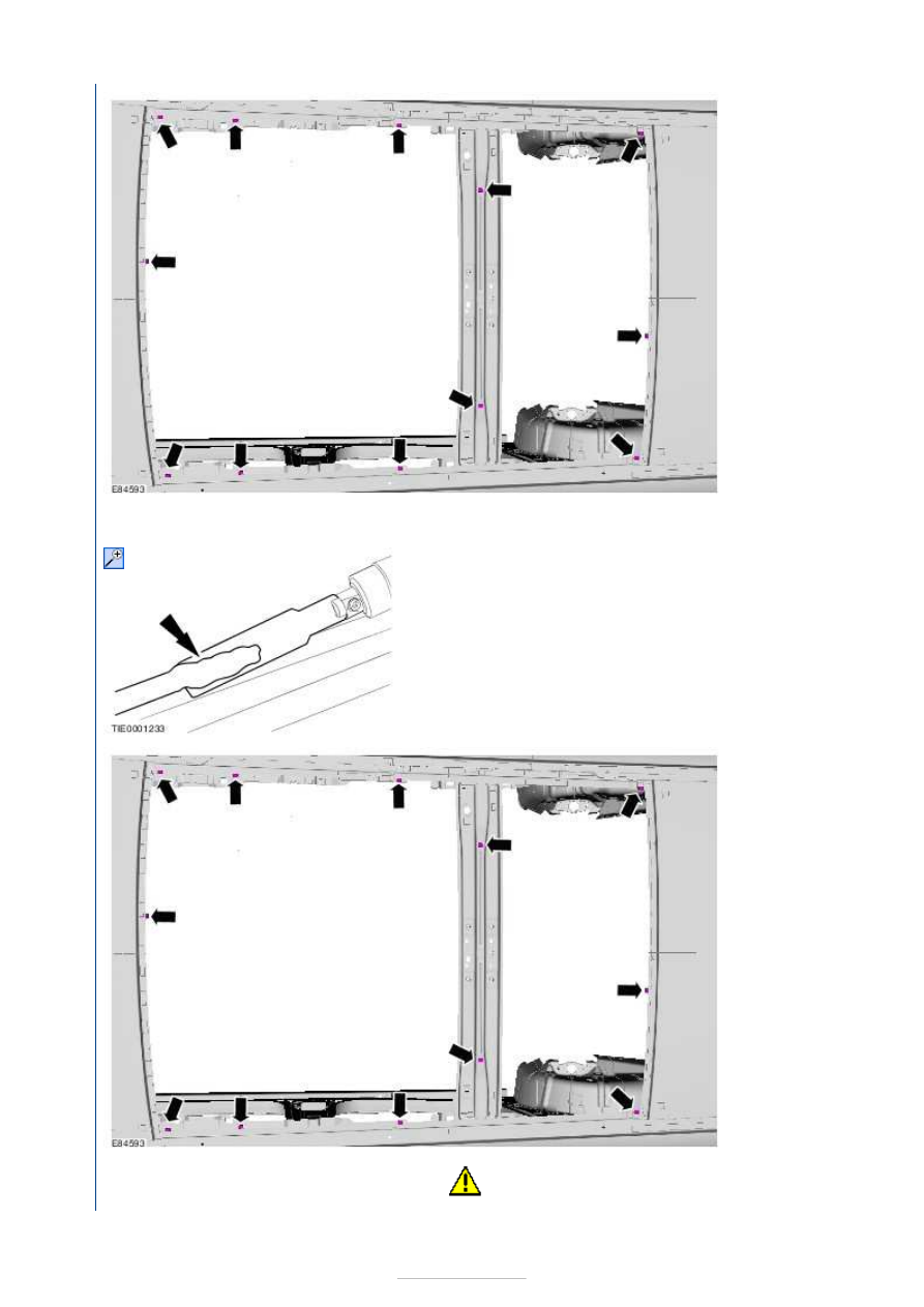
Carefully trim the remaining PU adhesive from the glass roof panel 
flange. 

General Equipment: 

Knife


2.

NOTE: Make sure that 
these components are 
installed to the noted 
removal position.

3.

CAUTION: Make sure that all bonding surfaces are free of 


moisture. 
NOTE: Touching the adhesive surface will impair rebonding.

Prepare the glass roof panel, glass roof panel flange and trimmed PU 
adhesive in accordance with the instructions supplied with the PU 
adhesive kit. 

General Equipment: 

Hot air gun


Material: 

Windshield Adhesive Kit (WSS-M11P57-A5)

4.

NOTE: Discard the first 100 mm of adhesive as this may have a 
reduced working time. 
NOTE: Make sure that any breakage in the continuous bead of 
adhesive is overlapped by 20 mm. 

Apply the PU adhesive in a continuous bead of between 8 and 10 mm 
in height to the glass roof panel flange along the bond line.

General Equipment: 

Direct glazing removal/replacement equipment

Material: 

Windshield Adhesive Kit (WSS-M11P57-A5)

5.

NOTE: This step requires the aid of another technician.

Press firmly and evenly into position. 

General Equipment: 

Direct glazing removal/replacement 

equipment


Using tape, secure the glass roof panel in the correct position 
until the PU adhesive has cured.  

6. If the ambient temperature falls below 10°C, apply warm air (25

continuously for 15 minutes. 

General Equipment: 

Hot air gun


Instrument Panel and Console - Instrument 
Panel—Vehicles Built Up To: 05/2007

S-MAX/Galaxy 2006.5 (02/2006

Removal and Installation 

General Equipment 

Removal 

All vehicles 

WARNINGS: 

The supplemental restraint system (SRS) is active for a certain length of time after the power 

supply has been disconnected. Wait for a minimum of 3 minutes before disconnecting or removing 
any SRS components. 

Wear safety goggles. 

Do not probe supplemental restraint system (SRS) electrical connectors. 

NOTE: Removal steps in this procedure may contain installation details. 

Flat-bladed screwdriver
Round-ended steel rule

1. Refer to: 

Supplemental Restraint System (SRS) Health and 

Safety Precautions

 (100-00 General Information, Description 

and Operation). 

2. Refer to: 

Battery Disconnect and Connect

 (414-01 Battery, 

Mounting and Cables, General Procedures). 

3. Remove the following items: 

1. Refer to: 

Floor Console Upper Section - Vehicles With: 

Center Armrest/Manually Adjusted Parking Brake

(501-12 Instrument Panel and Console, Removal and 
Installation). 

2. Refer to: 

Floor Console Upper Section - Vehicles With: 

Manually Adjusted Parking Brake, Vehicles Without: 
Center Armrest

 (501-12 Instrument Panel and 

Console, Removal and Installation). 

3. Refer to: 

Floor Console - Vehicles With: Electronic 

Parking Brake (EPB), VIN Plate Body Style Code: S

(501-12 Instrument Panel and Console, Removal and 
Installation). 

4. Refer to: 

Floor Console - Vehicles With: Electronic 

Parking Brake (EPB), VIN Plate Body Style Code: M

(501-12 Instrument Panel and Console, Removal and 
Installation). 

5. A-Pillar trim panels. 

Refer to: 

A-Pillar Trim Panel

 (501-05 Interior Trim and 

Ornamentation, Removal and Installation). 

6. Audio unit. 

Refer to: 

Audio Unit - Vehicles Built Up To: 05/2007

(415-01 Information and Entertainment System, 
Removal and Installation). 
Refer to: 

Audio Unit - Vehicles With: Travel Pilot EX

(415-01 Information and Entertainment System, 
Removal and Installation). 
Refer to: 

Audio Unit - Vehicles Built Up To: 05/2007, 

Vehicles With: Digital Versatile Disc (DVD) Navigation 
System

 (415-01 Information and Entertainment 

Vehicles with DVD navigation system with Touchscreen 

All vehicles 

System, Removal and Installation). 

7. Headlamp switch. 

Refer to: 

Headlamp Switch

 (417-01 Exterior Lighting, 

Removal and Installation). 

4. Remove the navigation system digital versatile disc (DVD) 

unit. 

Refer to: 

Navigation System Digital Versatile Disc (DVD) 

Unit

 (415-01 Information and Entertainment System, 

Removal and Installation). 

5. On both sides. 

6.  

7.  

8.  


Content   ..  928  929  930  931   ..