Ford Galaxy / Ford S-MAX. Manual - part 906
 

  Index      Ford     Ford Galaxy / Ford S-MAX - service repair manual 2006 year


Search            


Content   ..  904  905  906  907   ..


Ford Galaxy / Ford S-MAX. Manual - part 906


Yes 

GO to E2

.  

No 

REPAIR circuit SBB19A (BU/RD) or circuit SBB20P 
(GN/RD). TEST the system for normal operation. 

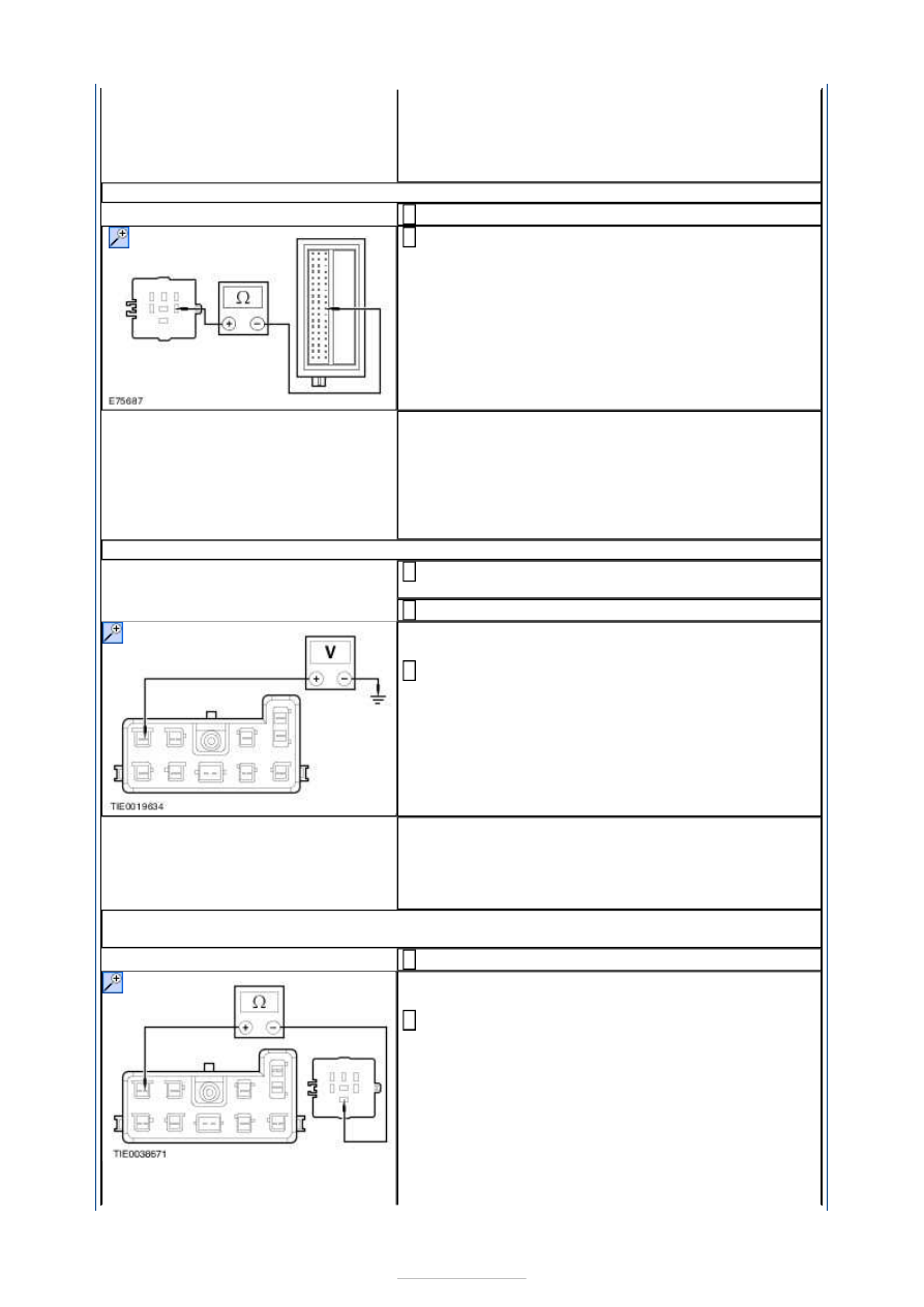
E2: CHECK THE HEATED SEAT RELAY CONTROL CIRCUIT FOR OPEN CIRCUIT

Disconnect Central Junction Box (CJB) C1BP02-B. 

Measure the resistance between the rear junction 
box relay RB1 pin 2, circuit CDC03A (BU), harness 

side and the CJB pin 45, circuit CDC03A (BU), 
harness side. 

Is the resistance less than 5 ohms? 
Yes 

INSTALL a new rear junction box relay RB1. If the 
problem persists, 

GO to E3

.  

No 

REPAIR circuit CDC03A (BU). TEST the system for 
normal operation. 

E3: CHECK FOR VOLTAGE TO THE INOPERATIVE HEATED SEAT

Disconnect Inoperative Power Seat C3HS03 or 
C3HS08. 

Ignition switch in position II. 

NOTE: Carry out the measurements on the 
inoperative seat. 

Measure the voltage between the: 

Front left heated seat C3HS03 pin 9, circuit 
B_CBR03A (GY), harness side and ground.  
or  
Front right heated seat C3HS08 pin 9, circuit 
B_CBR04A (VT), harness side and ground. 

Is the voltage greater than 10 volts? 
Yes 

GO to E5

.  

No 

GO to E4

.  

E4: CHECK FOR CONTINUITY BETWEEN THE HEATED SEAT RELAY AND THE HEATED 
SEAT MODULE

Ignition switch in position 0. 

NOTE: Carry out the measurements on the 
inoperative seat. 

Measure the resistance between the: 

Rear junction box relay RB1 pin 5, circuit 
B_CBR03A (GY), harness side and the climate 
controlled seat C3HS03 pin 9, circuit B_CBR03A 
(GY), harness side.  
or  
Rear junction box relay RB1 pin 5, circuit 
B_CBR04A (VT), harness side and the climate 
controlled seat C3HS08 pin 9, circuit B_CBR04A 


(VT), harness side. 

Is the resistance less than 5 ohms? 
Yes 

GO to E5

.  

No 

REPAIR circuit B_CBR03A (GY) or circuit B_CBR04A 
(VT). TEST the system for normal operation. 

E5: CHECK THE INOPERATIVE HEATED SEAT FOR GROUND

NOTE: Carry out the measurements on the 
inoperative seat. 

Measure the resistance between the:  

Front left heated seat C3HS03 pin 10, circuit 
GD134C (BK/VT), harness side and ground 
(LHD).  
and  
Front left heated seat C3HS03 pin 10, circuit 
GD140B (BK/GN), harness side and ground 
(RHD).  
or  
Front right heated seat C3HS08 pin 10, circuit 
GD140T (BK/GN), harness side and ground 
(LHD).  
and  
Front right heated seat C3HS08 pin 10, circuit 
GD134J (BK/VT), harness side and ground 
(RHD). 

Is the resistance less than 5 ohms? 
Yes 

GO to E6

.  

No 

REPAIR the relevant circuit 

E6: CHECK FOR VOLTAGE TO THE HEATED SEAT SWITCH

Disconnect Heated Seat Switch C3HS29. 

Ignition switch in position II. 

Measure the voltage between the: 

Heated seat switch C3HS29 pin 4, circuit CBP04F 
(VT), harness side and ground.  
and  
Heated seat switch C3HS29 pin 6, circuit SBP07D 
(WH/RD), harness side and ground. 

Are the voltages greater than 10 volts? 
Yes 

GO to E7

.  

No 

REPAIR circuit CBP04F (VT) or circuit SBP07D 
(WH/RD). TEST the system for normal operation. 

E7: CHECK THE HEATED SEAT SWITCH GROUND CIRCUIT

Measure the resistance between the heated seat 
switch C3HS29 pin 1, circuit GD133AP (BK), 

harness side and ground. 


Is the resistance less than 5 ohms? 
Yes 

GO to E8

.  

No 

REPAIR circuit GD133AP (BK). TEST the system for 
normal operation. 

E8: CHECK FOR CONTINUITY BETWEEN THE HEATED SEAT SWITCH AND THE HEATED 
SEAT

NOTE: Carry out the measurements on the 
inoperative seat. 

Measure the resistance between the: 

Front left heated seat C3HS03 pin 17, circuit 
CHS32C (BN), harness side and the heated seat 
switch C3HS29 pin 2, circuit CHS32B (BN), 
harness side.  
or  
Front right heated seat C3HS08 pin 17, circuit 
CHS32A (BN), harness side and the heated seat 
switch C3HS29 pin 2, circuit CHS32B (BN), 
harness side. 

Is the resistance less than 5 ohms? 
Yes 

INSTALL a new front seat cushion heater mat. TEST 
the system for normal operation. 

No 

REPAIR circuit CHS32A (BN), circuit CHS32B (BN) 
or circuit CHS32C (BN). TEST the system for normal 
operation. 

PINPOINT TEST F : THE HEATED SEAT IS INOPERATIVE - FRONT SEAT 

NOTE: Use a digital multimeter for all electrical measurements. 

TEST CONDITIONS

DETAILS/RESULTS/ACTIONS

F1: CHECK FOR VOLTAGE TO THE INOPERATIVE HEATED SEAT

Disconnect Inoperative Power Seat C3HS03 or 
C3HS08. 

NOTE: Carry out the measurements on the 
inoperative seat. 

Measure the voltage between the: 

Front left heated seat C3HS03 pin 9, circuit 
B_CBR03A (GY), harness side and ground.  
or  
Front right heated seat C3HS08 pin 9, circuit 
B_CBR04A (VT), harness side and ground. 

Is the voltage greater than 10 volts? 
Yes 


GO to F2

.  

No 

REPAIR circuit B_CBR03A (GY) or circuit B_CBR04A 
(VT). TEST the system for normal operation. 

F2: CHECK THE INOPERATIVE HEATED SEAT GROUND CIRCUIT

Ignition switch in position 0. 

NOTE: Carry out the measurements on the 
inoperative seat. 

Measure the resistance between the: 

Front left heated seat C3HS03 pin 10, circuit 
GD134C (BK/VT), harness side and ground 
(LHD).  
and  
Front left heated seat C3HS03 pin 10, circuit 
GD140B (BK/GN), harness side and ground 
(RHD).  
and  
Front left heated seat C3HS03 pin 18, circuit 
GD135J (BK/GY), harness side and ground (LHD). 

or 

Front right heated seat C3HS08 pin 10, circuit 
GD140T (BK/GN), harness side and ground 
(LHD).  
and  
Front right heated seat C3HS08 pin 10, circuit 
GD134J (BK/VT), harness side and ground 
(RHD).  
and  
Front right heated seat C3HS08 pin 18, circuit 
GD135S (BK/GY), harness side and ground 
(RHD). 

Is the resistance(s) less than 5 ohms? 
Yes 

GO to F3

.  

No 

REPAIR circuit GD134C (BK/VT), circuit GD140B 
(BK/GN), circuit GD135J (BK/GY), circuit GD140T 
(BK/GN), circuit GD134J (BK/VT), or circuit GD145D 
(BK/BU). TEST the system for normal operation. 

F3: CHECK CONTINUITY BETWEEN THE HEATED SEAT SWITCH AND THE HEATED SEAT

Disconnect Heated Seat Switch C3HS29. 

NOTE: Carry out the measurements on the 
inoperative seat. 

Measure the resistance between the: 

Front left heated seat C3HS03 pin 17, circuit 
CHS32C (BN), harness side and the heated seat 
switch C3HS29 pin 2, circuit CHS32B (BN), 
harness side.  
or  
Front right heated seat C3HS08 pin 17, circuit 
CHS32A (BN), harness side and the heated seat 
switch C3HS29 pin 2, circuit CHS32B (BN), 
harness side. 

Is the resistance less than 5 ohms? 
Yes 


Content   ..  904  905  906  907   ..