Ford Galaxy / Ford S-MAX. Manual - part 904
 

  Index      Ford     Ford Galaxy / Ford S-MAX - service repair manual 2006 year


Search            


Content   ..  902  903  904  905   ..


Ford Galaxy / Ford S-MAX. Manual - part 904


(501-20B Supplemental Restraint System, Description and Operation). 

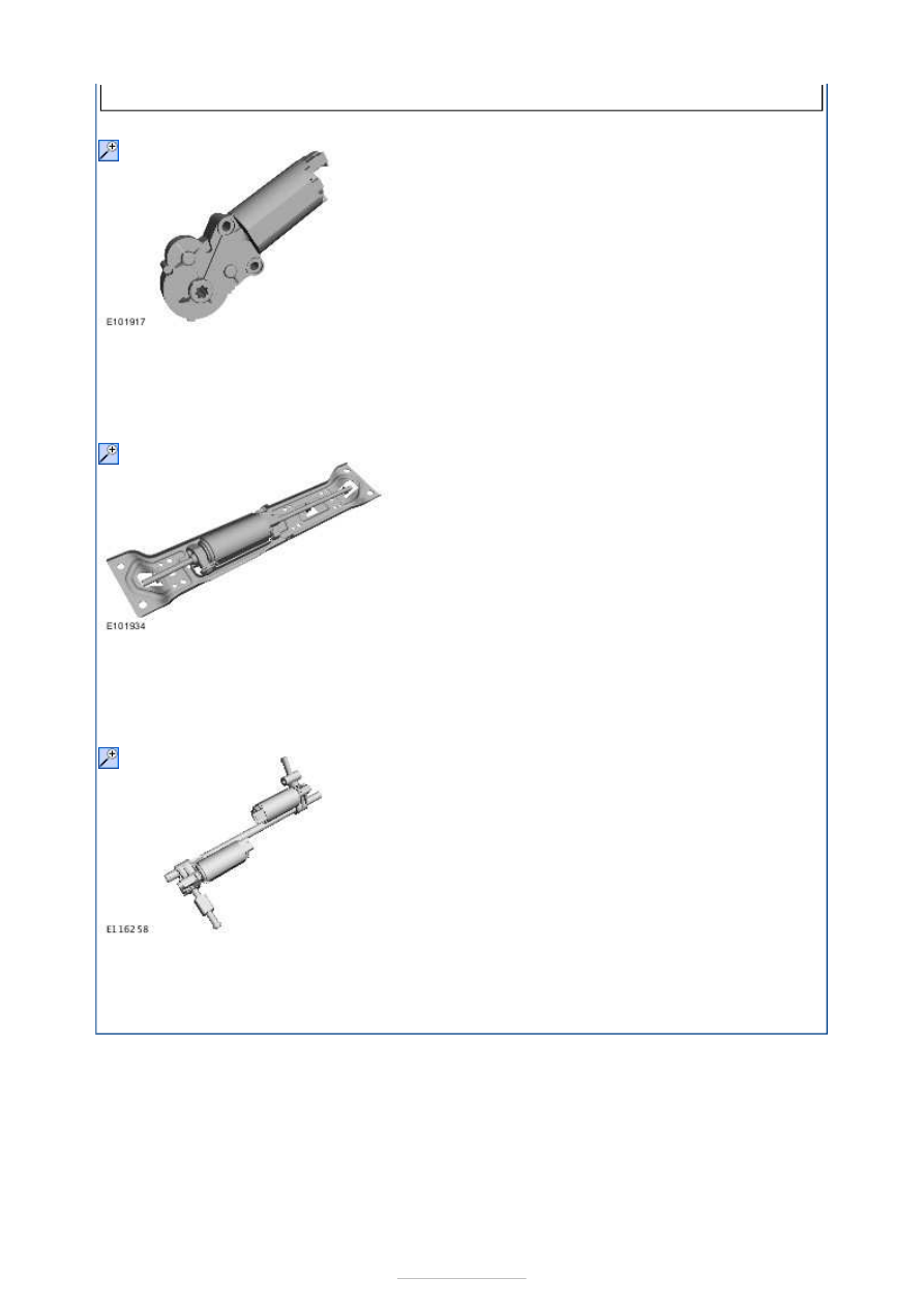
Servo motor, electrically adjustable backrest 

The electrically adjustable backrest servo motor consists of a DC motor with integral 
gearing (worm gear) and thermal cutout. If the servo motor stops under braking or jams, 
an internal thermal cut-out is tripped to interrupt the power supply to the servo motor. 

Servo motor, seat rails, forward and rearward motion 

The forward/back servo motor for the seat comprises a DC motor with thermal cutout. If 
the servo motor stops under braking or jams, an internal thermal cut-out is tripped to 
interrupt the power supply to the servo motor. 

Servo motors, seat height and seat angle electric adjustment  

The electrically adjustable seat height and seat angle servo motors consist of two DC 
motors with integral gearing (worm gear) and thermal cutout. If one of the servo motors 
stops under braking or jams, an internal thermal cut-out is tripped to interrupt the power 
supply to the servo motor. 


Seating - Seats

S-MAX/Galaxy 2006.5 (02/2006-)


Print


Diagnosis and Testing 

For Wiring Schematics and Connector Information, refer to the Wiring Diagram Cell 501-10. 

Principals of Operation 

The vehicle is equipped with either manually adjusted seats, bidirectional power height 
adjusted seats or full eight-way power adjusted seats for both driver and passenger. 
Vehicles equipped with the full eight-way power seat functionality are controlled by a single 
multifunction switch. In each power seat the switch is mounted onto the seat base panel 
within easy reach of the occupant. 

Seats with power height adjustment retain manual adjustment controls to attain seat 
adjustment. The bidirectional switch controls the operation of a single motor which 
depending on switch operation will either raise or lower the seat height through a series of 
mechanical linkages. 

Seats with full eight-way adjustment are able to adjust the seat position through any one of 
four different motors. Each seat function is controlled by a single multifunction switch, 
which in turn controls the operation of the bidirectional motor of the selected adjustment 
feature to achieve: 

Vertical adjustment of the front of the seat cushion;  
Vertical adjustment of the rear of the seat cushion;  
Horizontal seat movement along the seat track through a mechanical worm drive;  
Seat backrest position adjustment of the backrest rake angle. 

The driver seat with full eight-way power adjusted seats may have an option of driver seat 
memory. This option has an eight-way memory seat switch, additional memory motors and 
a memory module. 

Inspection and Verification 

1. 1. Verify the customer concern. 

2. 2. Visually inspect for obvious signs of mechanical or electrical damage. 

Visual Inspection Chart 

3. 3. If an obvious cause for an observed or reported concern is found, correct the cause 

(if possible) before proceeding to the next step 

4. 4. If the cause is not visually evident, verify the symptom and refer to the Symptom 

Chart. 

Symptom Chart 

Mechanical

Electrical

Damaged switch(es).  

Obstruction of ventilated seat air intake. 

Fuse(s).  

Wiring harness.  

Electrical connector(s).  

Motor(s).  

Switch(es). 

Symptom

Possible 

Sources

Action

The power seat is inoperative

Seat switch. 

*

CARRY OUT the Seat Switch 

Component Test. REFER to the Wiring 

*

Pinpoint Tests 

Diagrams. 

Circuit(s). 
Motor(s). 

*
*

GO to Pinpoint Test 

A. 


*

The power seat does not move 
horizontally

Seat switch. 

*

CARRY OUT the Seat Switch 

Component Test. REFER to the Wiring 
Diagrams. 

*

Circuit(s). 
Motor(s). 

*
*

GO to Pinpoint Test 

B. 


*

The power seat does not move 
vertically

Seat switch. 

*

CARRY OUT the Seat Switch 

Component Test. REFER to the Wiring 
Diagrams. 

*

Circuit(s). 
Motor(s) 

*
*

GO to Pinpoint Test 

C. 


*

The power seat does not recline

Seat switch. 

*

CARRY OUT the Seat Switch 

Component Test. REFER to the Wiring 
Diagrams. 

*

Circuit. 
Motor. 

*
*

GO to Pinpoint Test 

D. 


*

The heated seats are inoperative

Heated seat 

switch(es). 

*

CARRY OUT the Heated Seat Switch 

Component Test. REFER to the Wiring 
Diagrams. 

*

Circuit(s). 

*

GO to Pinpoint Test 

E. 


*

The heated seat is inoperative

Heated seat 

switch(es). 

*

CARRY OUT the Heated Seat Switch 

Component Test. REFER to the Wiring 
Diagrams. 

*

Circuit(s). 

*

GO to Pinpoint Test 

F. 


*

All climate controlled seats are 
inoperative/do not operate correctly

Heated seat 

switch(es). 

*

CARRY OUT the Heated Seat Switch 

Component Test. REFER to the Wiring 
Diagrams. 

*

Circuit(s). 

*

GO to Pinpoint Test 

G. 


*

A single climate controlled seat is 
inoperative/does not operate 
correctly

Heated seat 

switch(es). 

*

CARRY OUT the Heated Seat Switch 

Component Test. REFER to the Wiring 
Diagrams. 

*

Circuit(s). 

*

GO to Pinpoint Test 

H. 


*

PINPOINT TEST A : THE POWER SEAT IS INOPERATIVE - FRONT SEAT 

NOTE: Use a digital multimeter for all electrical measurements. 

TEST CONDITIONS

DETAILS/RESULTS/ACTIONS

A1: CHECK WHETHER DRIVER SEAT MEMORY INSTALLED

Ignition switch in position 0. 

Does the vehicle have driver seat memory? 
Yes 

GO to A2

.  

No 

GO to A4

.  

A2: CHECK THE VOLTAGE TO THE DRIVER SEAT MEMORY SWITCH

Disconnect Driver Seat Memory Switch C3HS03 or 
C3HS08. 

NOTE: Carry out the measurements on the 
inoperative seat. 

Measure the voltage between the:  

Driver seat memory switch C3HS03 pin 11, 
circuit C_SBR07A (WH/RD) harness side and 
ground.  

or  
Driver seat memory switch C3HS08 pin 11, 
circuit VR212A (YE/GN) harness side and ground. 

Is the voltage greater than 10 volts? 
Yes 

GO to A3

.  

No 

REPAIR circuit C_SBR07A (WH/RD) or circuit 
VR212A (YE/GN). TEST the system for normal 
operation. 

A3: CHECK THE DRIVER SEAT MEMORY SWITCH GROUND CIRCUIT FOR CONTINUITY

NOTE: Carry out the measurements on the 
inoperative seat. 

Measure the resistance between the:  

Driver seat memory switch C3HS03 pin 12, 
circuit GD135R (BK/GY) harness side and ground. 
or  
Driver seat memory switch C3HS08 pin 12, 
circuit RR155B (GY) harness side and ground. 

Is the resistance less than 5 ohms? 
Yes 

INSTALL a new driver seat memory switch. TEST 
the system for normal operation. 

No 

REPAIR circuit GD135R (BK/GY) or circuit RR155B 
(GY). TEST the system for normal operation. 

A4: CHECK THE VOLTAGE TO THE POWER SEAT SWITCH

Disconnect Inoperative Power Seat Switch C3HS03 
or C3HS08. 

NOTE: Carry out the measurements on the 
inoperative seat. 

Measure the voltage between the:  

Left-hand power seat switch C3HS03 pin 15, 
circuit SBR10A (YE/RD) harness side and ground. 
or  
Right-hand power seat memory switch C3HS08 
pin 15, circuit B_SBR09A (RD) harness side and 
ground. 

Is the voltage greater than 10 volts? 
Yes 

GO to A5

.  

No 

REPAIR circuit SBR10A (YE/RD) or circuit B_SBR09A 
(RD). TEST the system for normal operation. 

A5: CHECK THE POWER SEAT SWITCH GROUND CIRCUIT FOR CONTINUITY

Ignition switch in position 0. 

NOTE: Carry out the measurements on the 


Content   ..  902  903  904  905   ..