Ford Galaxy / Ford S-MAX. Manual - part 902
 

  Index      Ford     Ford Galaxy / Ford S-MAX - service repair manual 2006 year


Search            


Content   ..  900  901  902  903   ..


Ford Galaxy / Ford S-MAX. Manual - part 902


circuit CRD14A (WH/OG). 

Is the resistance less than 5 ohms? operation.  
Yes 

INSTALL a new heated exterior mirror glass. TEST 
the system for normal operation. 

No 

REPAIR circuit CRD13A (GN/VT) or circuit CRD14A 
(WH/OG). TEST the system for normal operation.  

PINPOINT TEST D : THE AUTO DIMMING MIRROR DOES NOT OPERATE 
CORRECTLY 

TEST CONDITIONS

DETAILS/RESULTS/ACTIONS

D1: CHECK FOR CONTINUITY BETWEEN THE AUTO-DIMMING INTERIOR MIRROR AND 
GROUND

NOTE: Use a digital multimeter for all electrical measurements. 

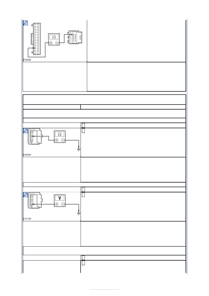
Disconnect Auto-dimming Interior Mirror C9PM05. 

Measure the resistance between the auto-dimming 
interior mirror C9PM05 pin 2, circuit GD138AA (BK/WH), 

harness side and ground.  

Is the resistance less than 5 ohms? 
Yes 

GO to D2

.  

No 

REPAIR circuit 91-AD15 (BK/OG). TEST the system for 
normal operation.  

D2: CHECK THE VOLTAGE TO THE AUTO-DIMMING INTERIOR MIRROR

Ignition switch in position II. 

Measure the voltage between the auto-dimming interior 
mirror C9PM05 pin 1, circuit B_CBP04A (VT), harness 

side and ground.  

Is the voltage greater than 10 volts? 
Yes 

GO to D3

.  

No 

REPAIR circuit B_CBP04A (VT). TEST the system for 
normal operation.  

D3: CHECK THE REVERSE CUT-OUT VOLTAGE TO THE AUTO-DIMMING INTERIOR 
MIRROR

Select N (NEUTRAL).  

Measure the voltage between the auto-dimming interior 
mirror C9PM05 pin 3, circuit RRD12A (BN), harness side 


and ground.  

Is any voltage present? 
Yes 

GO to D4

.  

No 

GO to D5

.  

D4: CHECK FOR VOLTAGE TO THE AUTO-DIMMING INTERIOR MIRROR

Ignition switch in position 0. 

Disconnect Transmission Switch C1ET47-A-1 or 
Transmission Switch C1ET47-C-1. 

Ignition switch in position II. 

Measure the voltage between the auto-dimming interior 
mirror C9PM05 pin 3, circuit RRD12A (BN), harness side 

and ground.  

Is any voltage present? 
Yes 

INSTALL a new transmission switch. TEST the system for 
normal operation.  

No 

REPAIR circuit RRD12A (BN). TEST the system for normal 
operation.  

D5: CHECK THE REVERSE CUT-OUT VOLTAGE TO THE AUTO-DIMMING INTERIOR 
MIRROR

Select R (REVERSE).  

Measure the voltage between the auto-dimming interior 
mirror C9PM05 pin 3, circuit RRD12A (BN), harness side 

and ground. 

Is the voltage greater than 10 volts?  
Yes 

INSTALL a new auto-dimming interior mirror.  
REFER to: Interior Rear View Mirror - Vehicles With: Rain 
Sensor/Autolamps (501-09 Rear View Mirrors, Removal 
and Installation). 
TEST the system for normal operation.  

No 

REPAIR circuit RRD12A (BN). TEST the system for normal 
operation.  

PINPOINT TEST E : THE POWER FOLDING MIRRORS DO NOT OPERATE/DO 
NOT OPERATE CORRECTLY 

TEST CONDITIONS

DETAILS/RESULTS/ACTIONS

E1: CHECK THE POWER FOLDING MIRRORS FOLD CIRCUIT

NOTE: Use a digital multimeter for all electrical measurements. 

Disconnect Driver Door Module C5PL01-B or 


Passenger Door Module C6PL01-B. 

Disconnect Driver Side Exterior Mirror C5PM26-A or 
Passenger Side Exterior Mirror C5PM31-A. 

Measure the resistance between the:  

Driver door module C5PL01-B pin 17, circuit 
CPM04A (VT/BN), harness side and the power 
folding mirror motor C5PM26-A pin 4, circuit 
CPM04A (VT/BN), harness side.  
Passenger door module C6PL01-B pin 17, circuit 
CPM07A (BN), harness side and the power folding 
mirror motor C5PM31-A pin 4, circuit CPM07A 
(BN), harness side.  

Is the resistance less than 5 ohms? 
Yes 

GO to E2

.  

No 

Driver side - REPAIR circuit CPM04A (VT/BN). TEST 
the system for normal operation.  
Passenger side - REPAIR circuit CPM07A (BN). TEST 
the system for normal operation.  

E2: CHECK THE POWER FOLDING MIRRORS UNFOLD CIRCUIT

Measure the resistance between the:  

Driver door module C5PL01-B pin 24, circuit 
CPM28A (BU/BN), harness side and the power 
folding mirror motor C5PM26-A pin 3, circuit 
CPM28A (BU/BN), harness side.  
Passenger door module C6PL01-B pin 24, circuit 
CPM33A (VT/BK), harness side and the power 
folding mirror motor C5PM31-A pin 3, circuit 
CPM33A (VT/BK), harness side.  

Is the resistance less than 5 ohms? 
Yes 

INSTALL a new power folding exterior mirror.  
REFER to: Exterior Mirror (501-09 Rear View Mirrors, 
Removal and Installation). 
TEST the system for normal operation.  

No 

Driver side - REPAIR circuit CPM28A (BU/BN). TEST 
the system for normal operation.  
Passenger side - REPAIR circuit CPM33A (VT/BK). 
TEST the system for normal operation.  


Rear View Mirrors - Interior Rear View 
Mirror—Vehicles With: 
Autowipers/Autolamps

S-MAX/Galaxy 2006.5 (02/2006-)


Print


Removal and Installation 

Removal 

NOTE: Removal steps in this procedure may contain installation details. 

All vehicles 

Vehicles with auto-dimming interior mirror 

All vehicles 

Installation 

1.  

2.  

3.  

4.  

1. To install, reverse the removal procedure. 


Content   ..  900  901  902  903   ..