Ford Galaxy / Ford S-MAX. Manual - part 900
 

  Index      Ford     Ford Galaxy / Ford S-MAX - service repair manual 2006 year


Search            


Content   ..  898  899  900  901   ..


Ford Galaxy / Ford S-MAX. Manual - part 900


Exterior Trim and Ornamentation - 
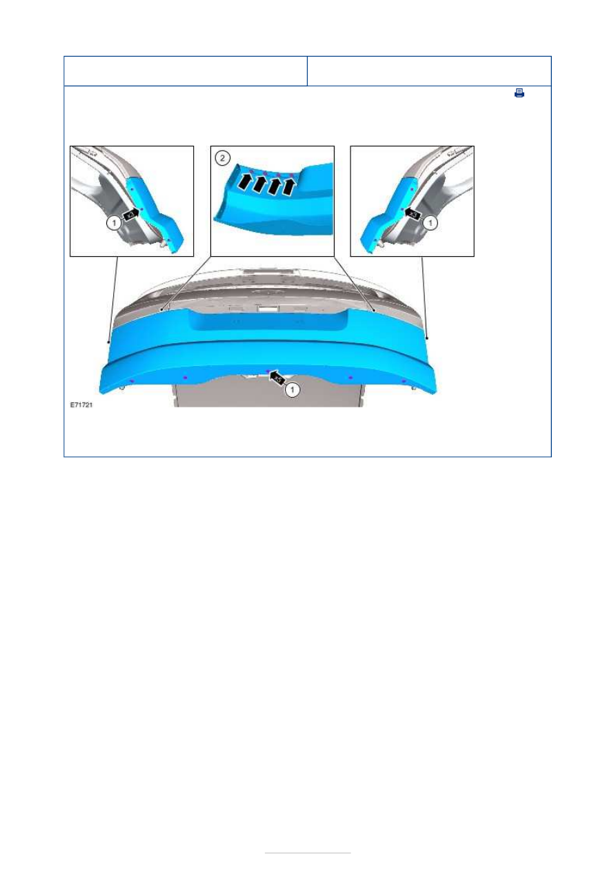
Liftgate Moulding

S-MAX/Galaxy 2006.5 (02/2006-)


Print


Removal and Installation 

Removal 

Installation 

1.  

1. To install, reverse the removal procedure. 


Rear View Mirrors - Rear View Mirrors

S-MAX/Galaxy 2006.5 (02/2006-)


Print


Description and Operation 

Auto-dimming Interior Mirror 

When the ignition is switched on the auto-dimming interior mirror will darken automatically 
depending on the amount of light shining into the vehicle through the rear window glass. 
The auto-dimming feature will turn off when reverse gear is selected. 

The auto-dimming feature on the interior rear view mirror will not operate correctly if light 
through the rear window glass is obstructed. 

Rear View Mirrors - Rear View Mirrors

S-MAX/Galaxy 2006.5 (02/2006-)


Print


Diagnosis and Testing 

Inspection and Verification 

1. 1. Verify the customer concern. 

2. 2. Visually inspect for obvious signs of mechanical or electrical damage. 

Visual Inspection Chart 

3. 3. If an obvious cause for an observed or reported concern is found, correct the cause 

(if possible) before proceeding to the next step 

4. 4. If the cause is not visually evident, verify the symptom and refer to the Symptom 

Chart. 

Symptom Chart 

Mechanical

Electrical

Exterior mirror(s)

Fuse(s)

Door module

Electrical connector(s)

Switch(es)

Symptom

Possible Sources

Action

The mirrors are inoperative

Exterior mirror switch. 
LIN Bus. 

*
*

REFER to WDS. 

*

A single mirror is inoperative

Exterior mirror switch. 
Door module. 
LIN Bus. 

*
*
*

REFER to WDS. 

*

Circuit(s). 

*

GO to Pinpoint 

Test 

A. 


*

A single mirror does not function with switch 
logic

Exterior mirror switch. 
Door module. 
LIN Bus. 

*
*
*

REFER to WDS. 

*

Circuit(s). 
Exterior mirror motor

(s). 

*
*

GO to Pinpoint 

Test 

B. 


*

The heated exterior mirror is inoperative

Heated rear window 

switch. 

Door module. 
LIN Bus. 

*

*
*

REFER to WDS. 

*

Circuit(s). 
Heated mirror element

(s). 

*
*

GO to Pinpoint 

Test 

C. 


*

The auto dimming mirror does not operate 
correctly

Auto-dimming interior 

mirror. 

Circuit(s). 

*

*

GO to Pinpoint 

Test 

D. 


*

The power folding mirrors do not operate/ do not 
operate correctly

Exterior mirror switch. 
Power fold mirror 

switch. 

Door module. 
Central junction box 

(CJB). 

LIN Bus. 

*
*

*
*

*

REFER to WDS. 

*

Power fold mirror(s). 

*

GO to Pinpoint 

*

Pinpoint Tests 

Circuit(s). 

*

Test 

E. 


PINPOINT TEST A : A SINGLE MIRROR IS INOPERATIVE 

TEST CONDITIONS

DETAILS/RESULTS/ACTIONS

A1: CHECK FOR CONTINUITY BETWEEN THE INOPERATIVE EXTERIOR MIRROR AND 
THE DOOR MODULE

NOTE: Use a digital multimeter for all electrical measurements. 

Disconnect Inoperative Exterior Mirror C5PM26 or 
C5PM31. 

Disconnect Driver Door Module C5PL01-B or 
Passenger Door Module C6PL01-B. 

Measure the resistance between the:  

Driver Exterior Mirror 

Driver door module C5PL01-B pin 9, circuit 
CPM03A (BU/WH), harness side and the driver side 
exterior mirror C5PM26 pin A-2, circuit CPM03A 
(BU/WH), harness side. 

Passenger Exterior Mirror 

Passenger door module C6PL01-B pin 9, circuit 
CPM06A (GN/WH), harness side and the driver side 
exterior mirror C5PM26 pin A-2, circuit CPM06A 
(GN/WH), harness side. 

Is the resistance less than 5 ohms?  
Yes 

INSTALL a new exterior mirror.  
REFER to: Exterior Mirror (501-09 Rear View Mirrors, 
Removal and Installation). 
TEST the system for normal operation.  

No 

REPAIR circuit CPM03A (BU/WH) or circuit CPM06A 
(GN/WH). TEST the system for normal operation.  

PINPOINT TEST B : A SINGLE MIRROR DOES NOT FUNCTION WITH 
SWITCH LOGIC 

TEST CONDITIONS

DETAILS/RESULTS/ACTIONS

B1: CHECK THE EXTERIOR MIRROR FUNCTIONS WITH SWITCH LOGIC

NOTE: Use a digital multimeter for all electrical measurements. 

Operate the exterior mirror switch. 

Does the exterior mirror function with switch logic? 
Yes 

VERIFY the customer concern. 

No 

Driver side exterior mirror UP/DOWN inoperative - 

GO to B2

.  

Driver side exterior mirror LEFT/RIGHT inoperative - 

GO to B4

.  

Passenger side exterior mirror UP/DOWN inoperative 

GO to B6

.  

Passenger side exterior mirror LEFT/RIGHT 
inoperative - 

GO to B8

.  

B2: CHECK THE DRIVER SIDE EXTERIOR MIRROR UP/DOWN CIRCUIT

Ignition switch in position 0. 


Content   ..  898  899  900  901   ..