Ford Galaxy / Ford S-MAX. Manual - part 901
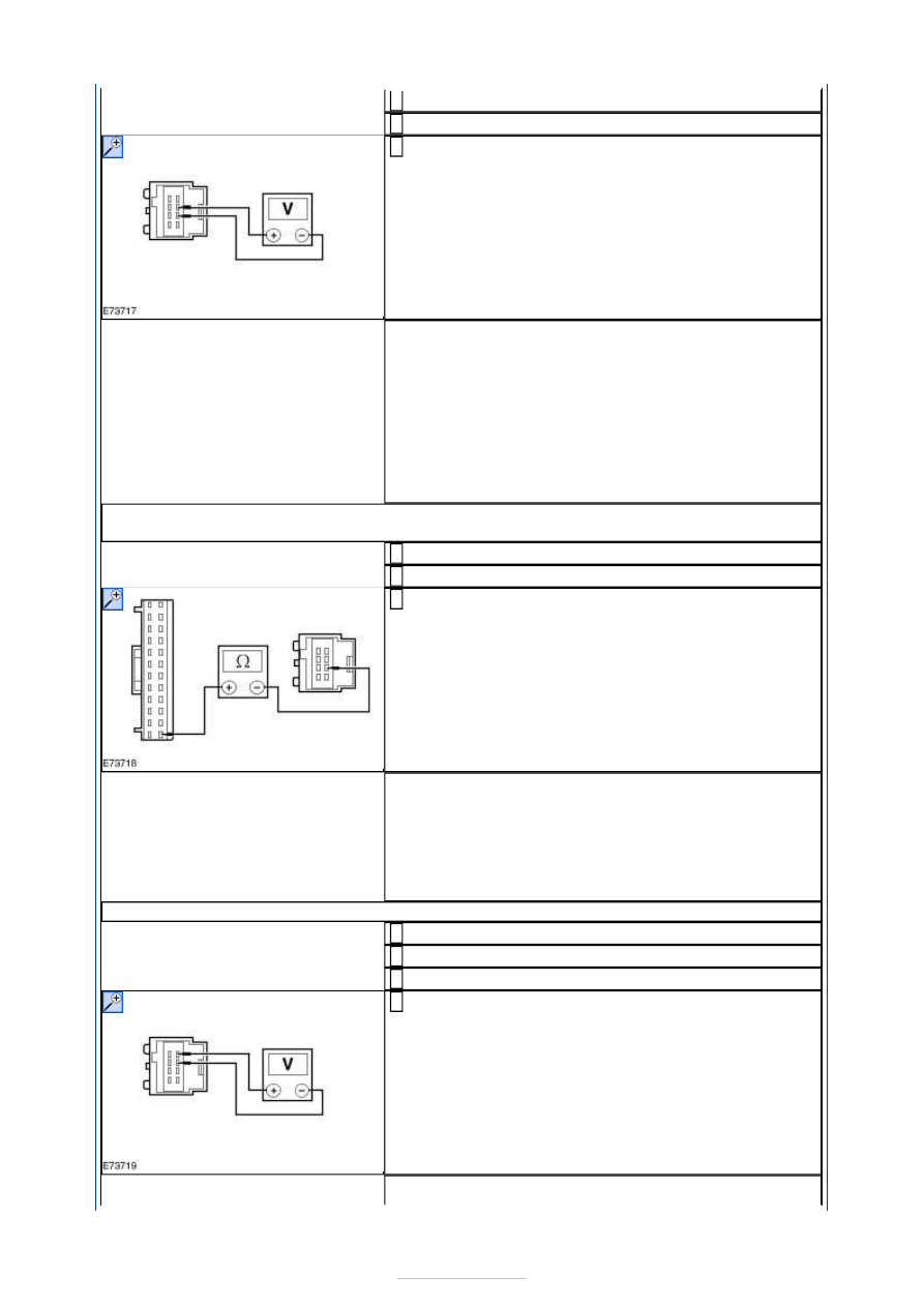
Disconnect Driver Side Exterior Mirror C5PM26-A.
2
Ignition switch in position II.
3
Select the driver side exterior mirror. While
operating the exterior mirror switch UP and DOWN,
measure the voltage between the driver side exterior
mirror C5PM26-A pin 2, circuit CPM03A (BU/WH),
harness side and the driver side exterior mirror
C5PM26-A pin 3, circuit CPM28A (BU/BN), harness
side.
4
Is the voltage greater than 10 volts when the exterior
mirror switch is moved to the UP position and is the
polarity reversed when moved to the DOWN position?
Yes
INSTALL a new driver side exterior mirror.
REFER to: Exterior Mirror (501-09 Rear View Mirrors,
Removal and Installation).
TEST the system for normal operation.
No
GO to B3
.
B3: CHECK THE DRIVER SIDE EXTERIOR MIRROR UP/DOWN CIRCUIT FOR
CONTINUITY
Ignition switch in position 0.
1
Disconnect Driver Door Module C5PL01-B.
2
Measure the resistance between the driver door
module C5PL01-B pin 24, circuit CPM29A (GN),
harness side and the driver side exterior mirror
C5PM26-A pin 3, circuit CPM28A (BU/BN), harness
side.
3
Is the resistance less than 5 ohms?
Yes
VERIFY the customer concern. TEST the system for
normal operation.
No
REPAIR circuit CPM28A (BU/BN). TEST the system for
normal operation.
B4: CHECK THE DRIVER SIDE EXTERIOR MIRROR LEFT/RIGHT CIRCUIT
Ignition switch in position 0.
1
Disconnect Driver Side Exterior Mirror C5PM26-A.
2
Ignition switch in position II.
3
Select the driver side exterior mirror. While
operating the exterior mirror switch LEFT and RIGHT,
measure the voltage between the driver side exterior
mirror C5PM26-A pin 1, circuit CPM29A (GN), harness
side and the driver side exterior mirror C5PM26-A pin
2, circuit CPM29A (GN), harness side.
4
Is the voltage greater than 10 volts when the exterior