Ford Galaxy / Ford S-MAX. Manual - part 841
 

  Index      Ford     Ford Galaxy / Ford S-MAX - service repair manual 2006 year


Search            


Content   ..  839  840  841  842   ..


Ford Galaxy / Ford S-MAX. Manual - part 841


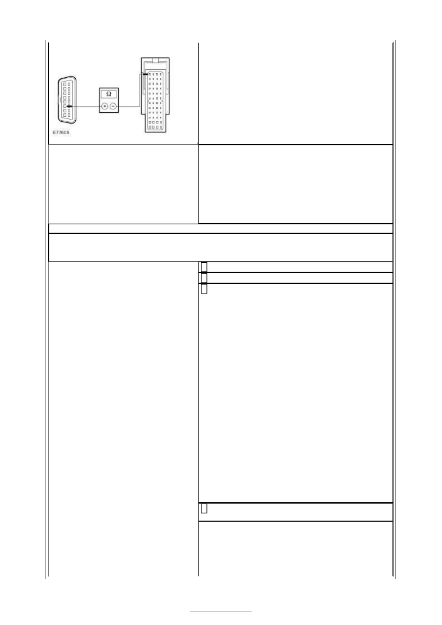
Is a resistance of less than 2 Ohms registered? 
Yes 

CHECK the PCM and RENEW if necessary. CHECK 
the operation of the system. 

No 

LOCATE and REPAIR the open in the respective 
circuit between the PCM and DLC by using the 
wiring diagrams. CHECK the operation of the 
system. 

AK30: PERFORM NETWORK TEST

NOTE: The number of modules connected to the CAN bus depends on the equipment 
levels of the vehicle. Therefore, not every vehicle will have all the modules mentioned 
below. 

Connect the ground cable to the battery. 

Connect the diagnostic tool. 

Disconnect a listed component, then proceed 
with the following test step: 

ESP module: C1CA01 

Power steering pump module: C1CS04 

Parking brake module: C4CB01 

Lights control module (LCM): C2LF23-A 

Collision warning module: C2FM01 

Steering wheel module: C2LS41 

Shock absorber control module: C4CD01-B 

Yaw rate / lateral acceleration sensor: C3CA09 

Transmission control unit (TCM) - vehicles with 
automatic transmission: C1ET34 

Generic Electronic Module (GEM): C1BP02-C 

Select the vehicle with the Ford approved 
diagnostic tool. 

Is it possible to establish communications with the 
PCM? 
Yes 

The component last disconnected is the cause of 
the concern; CHECK and if necessary RENEW the 
component. CHECK the operation of the system. 


No 

- If not all the listed components are 
disconnected:Key in OFF position. DISCONNECT 
the next component (go to test step 3). 
- If all the listed components are 
disconnected:

GO to AK31

.  

AK31: CHECK THE HS CAN BUS FOR A SHORT TO VOLTAGE SUPPLY

Ignition switch in position 0. 

Disconnect - Vehicles with a 2.0L diesel engine: 
Connector C1E108-D from the PCM. 

Disconnect - Vehicles with a 2.0L engine: 
Connector C1E104-E from the PCM. 

Disconnect - Vehicles with a 2.5L engine: 
Connector C1E108-B from the PCM. 

Disconnect - Vehicles with a 1.8L diesel engine: 
Connector C1E108-K from the PCM. 

Disconnect - Vehicles with a 1.6L Duratec-16V 
(Sigma) engine: Connector C1E104-J from the 

PCM. 

Disconnect - Vehicles with a 3.0L Duratec-VE 
(VE6) engine: Connector C1E109-B from the 

PCM. 

Disconnect - Vehicles with a 2.2L diesel engine: 
Connector C1E108-H from the PCM. 

Ignition switch in position II. 

Measure the voltage between the DLC, connector 
C3DB04, pin 6, circuit VDB04L (WH/BU), wiring 

harness side and ground. 

10 

Is a voltage measured? 
Yes 

LOCATE and REPAIR the short to voltage supply 
in the relevant circuit with the aid of the Wiring 
Diagrams. CHECK the operation of the system. 

No 

GO to AK32

.  

AK32: CHECK THE HS CAN BUS FOR A SHORT TO VOLTAGE SUPPLY

Measure the voltage between the DLC, connector 


C3DB04, pin 14, circuit VDB05Z (WH), wiring 
harness side and ground. 

Is a voltage measured? 
Yes 

LOCATE and REPAIR the short to voltage supply 
in the relevant circuit with the aid of the Wiring 
Diagrams. CHECK the operation of the system. 

No 

GO to AK33

.  

AK33: CHECK THE HS CAN BUS FOR A SHORT TO GROUND

Ignition switch in position 0. 

Measure the resistance between the DLC, 
connector C3DB04, pin 14, circuit VDB05Z (WH), 

wiring harness side and ground. 

Is a resistance of more than 10,000 Ohm measured? 
Yes 

GO to AK34

.  

No 

LOCATE and REPAIR the short to ground in the 
relevant circuit with the aid of the Wiring 
Diagrams. CHECK the operation of the system. 

AK34: CHECK THE HS CAN BUS FOR A SHORT TO GROUND

Measure the resistance between the DLC, 
connector C3DB04, pin 6, circuit VDB04L 

(WH/BU), wiring harness side and ground. 

Is a resistance of more than 10,000 Ohm measured? 
Yes 

GO to AK35

.  

No 

LOCATE and REPAIR the short to ground in the 
relevant circuit with the aid of the Wiring 
Diagrams. CHECK the operation of the system. 

AK35: CHECK THE HS CAN BUS FOR SHORT CIRCUIT

Measure the resistance between the DLC, 
connector C3DB04, pin 6, circuit VDB04L 

(WH/BU), wiring harness side and pin 14, circuit 
VDB05Z (WH), wiring harness side. 


Is a resistance of more than 10,000 Ohm measured? 
Yes 

CHECK the PCM and RENEW if necessary. CHECK 
the operation of the system. 

No 

LOCATE and REPAIR the short circuit in the HS 
CAN Bus using the Wiring Diagrams. CHECK the 
operation of the system. 

PINPOINT TEST AL : FAULTY COMMUNICATIONS BETWEEN THE MODULES 
- MM CAN BUS 

CAUTION: The measurements below may only be performed using the Ford 

approved diagnostic tool digital multimeter. Failure to observe this instruction can lead to 
damage. 

TEST CONDITIONS

DETAILS/RESULTS/ACTIONS

AL1: CHECK FUSE F26

Ignition switch in position 0. 

CHECK Fuse F26 (CJB). 

Is the fuse OK? 
Yes 

GO to AL2

.  

No 

RENEW fuse F26 (5 A). CHECK the operation of the 
system. If the fuse blows again, LOCATE and 
REPAIR the short using the Wiring Diagrams. 

AL2: CHECK THE VOLTAGE AT FUSE F26

Connect Fuse F26 (CJB). 

Measure the voltage between fuse F26 (5 A) and 
ground. 

Does the meter display battery voltage? 
Yes 

GO to AL3

.  

No 

REPAIR the voltage supply to fuse F26 with the aid 
of the Wiring Diagrams. CHECK the operation of the 
system. 

AL3: CHECK THE VOLTAGE AT THE DATA LINK CONNECTOR (DLC)

Measure the voltage between the DLC, connector 
C3DB04, pin 16, circuit SBP26A (YE/RD), wiring 

harness side and ground. 

Does the meter display battery voltage? 


Content   ..  839  840  841  842   ..