Ford Galaxy / Ford S-MAX. Manual - part 840
 

  Index      Ford     Ford Galaxy / Ford S-MAX - service repair manual 2006 year


Search            


Content   ..  838  839  840  841   ..


Ford Galaxy / Ford S-MAX. Manual - part 840


Yes 

CHECK the PCM and RENEW if necessary. CHECK 
the operation of the system. 

No 

LOCATE and REPAIR the open in the respective 
circuit between the PCM and DLC by using the 
wiring diagrams. CHECK the operation of the 
system. 

AK20: CHECK FOR OPEN CIRCUIT BETWEEN THE PCM AND THE DATA LINK 
CONNECTOR (DLC)

CAUTION: The following measurement must only be performed using the Ford 

approved diagnostic tool digital multimeter. Failure to observe this instruction can lead to 
damage. 

Disconnect Connector C1E108-B from the PCM. 

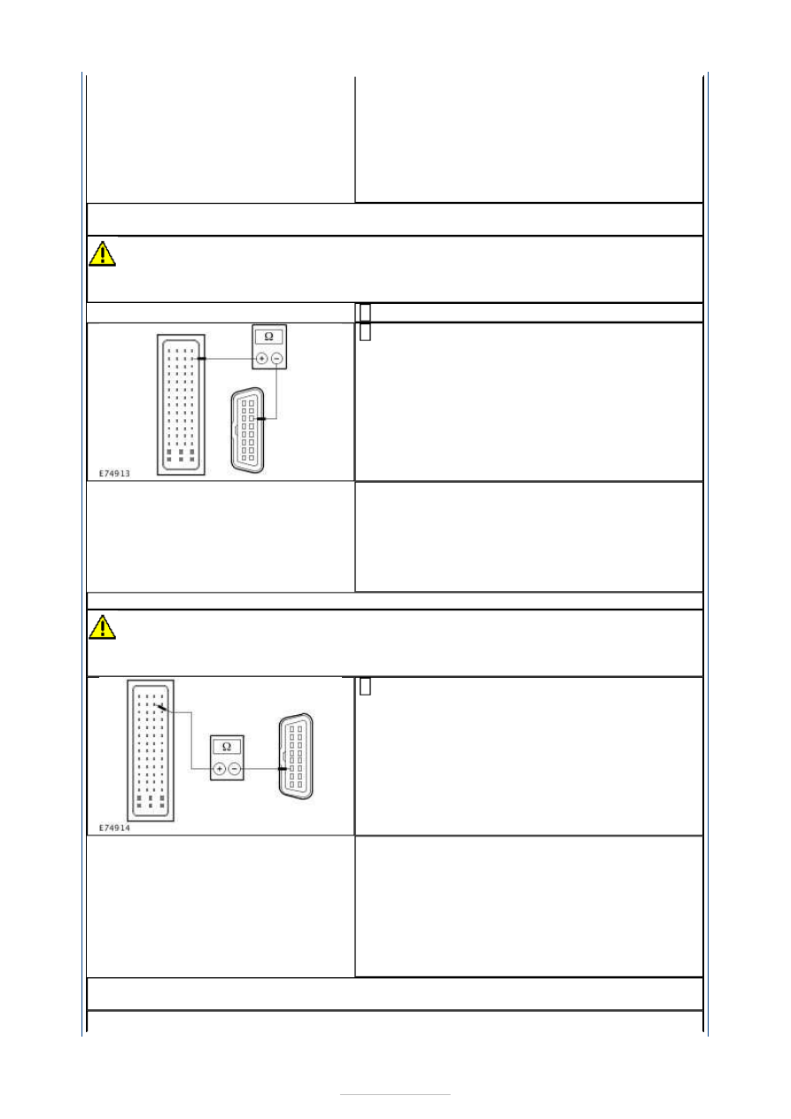
Measure the resistance between the PCM, 
connector C1E108-B, pin 57, circuit VDB04AK 

(WH/BU), wiring harness side and the DLC, 
connector C3DB04, pin 6, circuit VDB04L 
(WH/BU), wiring harness side. 

Is a resistance of less than 2 Ohms registered? 
Yes 

GO to AK21

.  

No 

LOCATE and REPAIR the open circuit between the 
PCM and the DLC using the Wiring Diagrams. 
CHECK the operation of the system. 

AK21: CHECK THE CIRCUIT BETWEEN THE PCM AND THE DLC FOR OPEN CIRCUIT

CAUTION: The following measurement must only be performed using the Ford 

approved diagnostic tool digital multimeter. Failure to observe this instruction can lead to 
damage. 

Measure the resistance between the PCM, 
connector C1E108-B, pin 44, circuit VDB05A 

(WH), wiring harness side and the DLC, 
connector C3DB04, pin 14, circuit VDB05Z (WH), 
wiring harness side. 

Is a resistance of less than 2 Ohms registered? 
Yes 

CHECK the PCM and RENEW if necessary. CHECK 
the operation of the system. 

No 

LOCATE and REPAIR the open in the respective 
circuit between the PCM and DLC by using the 
wiring diagrams. CHECK the operation of the 
system. 

AK22: CHECK FOR OPEN CIRCUIT BETWEEN THE PCM AND THE DATA LINK 
CONNECTOR (DLC)


CAUTION: The following measurement must only be performed using the Ford 

approved diagnostic tool digital multimeter. Failure to observe this instruction can lead to 
damage. 

Disconnect Connector C1E108-K from the PCM. 

Measure the resistance between the PCM, 
connector C1E108-K, pin A4, circuit VDB04AE 

(WH/BU), wiring harness side and the DLC, 
connector C3DB04, pin 6, circuit VDB04L 
(WH/BU), wiring harness side. 

Is a resistance of less than 2 Ohms registered? 
Yes 

GO to AK23

.  

No 

LOCATE and REPAIR the open circuit between the 
PCM and the DLC using the Wiring Diagrams. 
CHECK the operation of the system. 

AK23: CHECK THE CIRCUIT BETWEEN THE PCM AND THE DLC FOR OPEN CIRCUIT

CAUTION: The following measurement must only be performed using the Ford 

approved diagnostic tool digital multimeter. Failure to observe this instruction can lead to 
damage. 

Measure the resistance between the PCM, 
connector C1E108-K, pin A3, circuit VDB05AH 

(WH), wiring harness side and the DLC, 
connector C3DB04, pin 14, circuit VDB05Z (WH), 
wiring harness side. 

Is a resistance of less than 2 Ohms registered? 
Yes 

CHECK the PCM and RENEW if necessary. CHECK 
the operation of the system. 

No 

LOCATE and REPAIR the open in the respective 
circuit between the PCM and DLC by using the 
wiring diagrams. CHECK the operation of the 
system. 

AK24: CHECK FOR OPEN CIRCUIT BETWEEN THE PCM AND THE DATA LINK 
CONNECTOR (DLC)

CAUTION: The following measurement must only be performed using the Ford 

approved diagnostic tool digital multimeter. Failure to observe this instruction can lead to 
damage. 

Disconnect Connector C1E104-J from the PCM. 

Measure the resistance between the PCM, 
connector C1E104-J, pin D4, circuit VDB04AX 

(WH/BU), wiring harness side and the DLC, 
connector C3DB04, pin 6, circuit VDB04L 
(WH/BU), wiring harness side. 


Is a resistance of less than 2 Ohms registered? 
Yes 

GO to AK25

.  

No 

LOCATE and REPAIR the open circuit between the 
PCM and the DLC using the Wiring Diagrams. 
CHECK the operation of the system. 

AK25: CHECK THE CIRCUIT BETWEEN THE PCM AND THE DLC FOR OPEN CIRCUIT

CAUTION: The following measurement must only be performed using the Ford 

approved diagnostic tool digital multimeter. Failure to observe this instruction can lead to 
damage. 

Measure the resistance between the PCM, 
connector C1E104-J, pin E3, circuit VDB05BA 

(WH), wiring harness side and the DLC, 
connector C3DB04, pin 14, circuit VDB05Z (WH), 
wiring harness side. 

Is a resistance of less than 2 Ohms registered? 
Yes 

CHECK the PCM and RENEW if necessary. CHECK 
the operation of the system. 

No 

LOCATE and REPAIR the open in the respective 
circuit between the PCM and DLC by using the 
wiring diagrams. CHECK the operation of the 
system. 

AK26: CHECK FOR OPEN CIRCUIT BETWEEN THE PCM AND THE DATA LINK 
CONNECTOR (DLC)

CAUTION: The following measurement must only be performed using the Ford 

approved diagnostic tool digital multimeter. Failure to observe this instruction can lead to 
damage. 

Disconnect Connector C1E109-B from the PCM. 

Measure the resistance between the PCM, 
connector C1E109-B, pin 54, circuit VDB04BC 

(WH/BU), wiring harness side and the DLC, 
connector C3DB04, pin 6, circuit VDB04L 
(WH/BU), wiring harness side. 

Is a resistance of less than 2 Ohms registered? 
Yes 

GO to AK27

.  

No 

LOCATE and REPAIR the open circuit between the 
PCM and the DLC using the Wiring Diagrams. 


CHECK the operation of the system. 

AK27: CHECK THE CIRCUIT BETWEEN THE PCM AND THE DLC FOR OPEN CIRCUIT

CAUTION: The following measurement must only be performed using the Ford 

approved diagnostic tool digital multimeter. Failure to observe this instruction can lead to 
damage. 

Measure the resistance between the PCM, 
connector C1E109-B, pin 41, circuit VDB05BC 

(WH), wiring harness side and the DLC, 
connector C3DB04, pin 14, circuit VDB05Z (WH), 
wiring harness side. 

Is a resistance of less than 2 Ohms registered? 
Yes 

CHECK the PCM and RENEW if necessary. CHECK 
the operation of the system. 

No 

LOCATE and REPAIR the open in the respective 
circuit between the PCM and DLC by using the 
wiring diagrams. CHECK the operation of the 
system. 

AK28: CHECK FOR OPEN CIRCUIT BETWEEN THE PCM AND THE DATA LINK 
CONNECTOR (DLC)

CAUTION: The following measurement must only be performed using the Ford 

approved diagnostic tool digital multimeter. Failure to observe this instruction can lead to 
damage. 

Disconnect Connector C1E108-H from the PCM. 

Measure the resistance between the PCM, 
connector C1E108-H, pin A2, circuit VDB04AV 

(WH/BU), wiring harness side and the DLC, 
connector C3DB04, pin 6, circuit VDB04L 
(WH/BU), wiring harness side. 

Is a resistance of less than 2 Ohms registered? 
Yes 

GO to AK29

.  

No 

LOCATE and REPAIR the open circuit between the 
PCM and the DLC using the Wiring Diagrams. 
CHECK the operation of the system. 

AK29: CHECK THE CIRCUIT BETWEEN THE PCM AND THE DLC FOR OPEN CIRCUIT

CAUTION: The following measurement must only be performed using the Ford 

approved diagnostic tool digital multimeter. Failure to observe this instruction can lead to 
damage. 

Measure the resistance between the PCM, 
connector C1E108-H, pin A1, circuit VDB05AW 

(WH), wiring harness side and the DLC, 
connector C3DB04, pin 14, circuit VDB05Z (WH), 
wiring harness side. 


Content   ..  838  839  840  841   ..