Ford Galaxy / Ford S-MAX. Manual - part 837
 

  Index      Ford     Ford Galaxy / Ford S-MAX - service repair manual 2006 year


Search            


Content   ..  835  836  837  838   ..


Ford Galaxy / Ford S-MAX. Manual - part 837


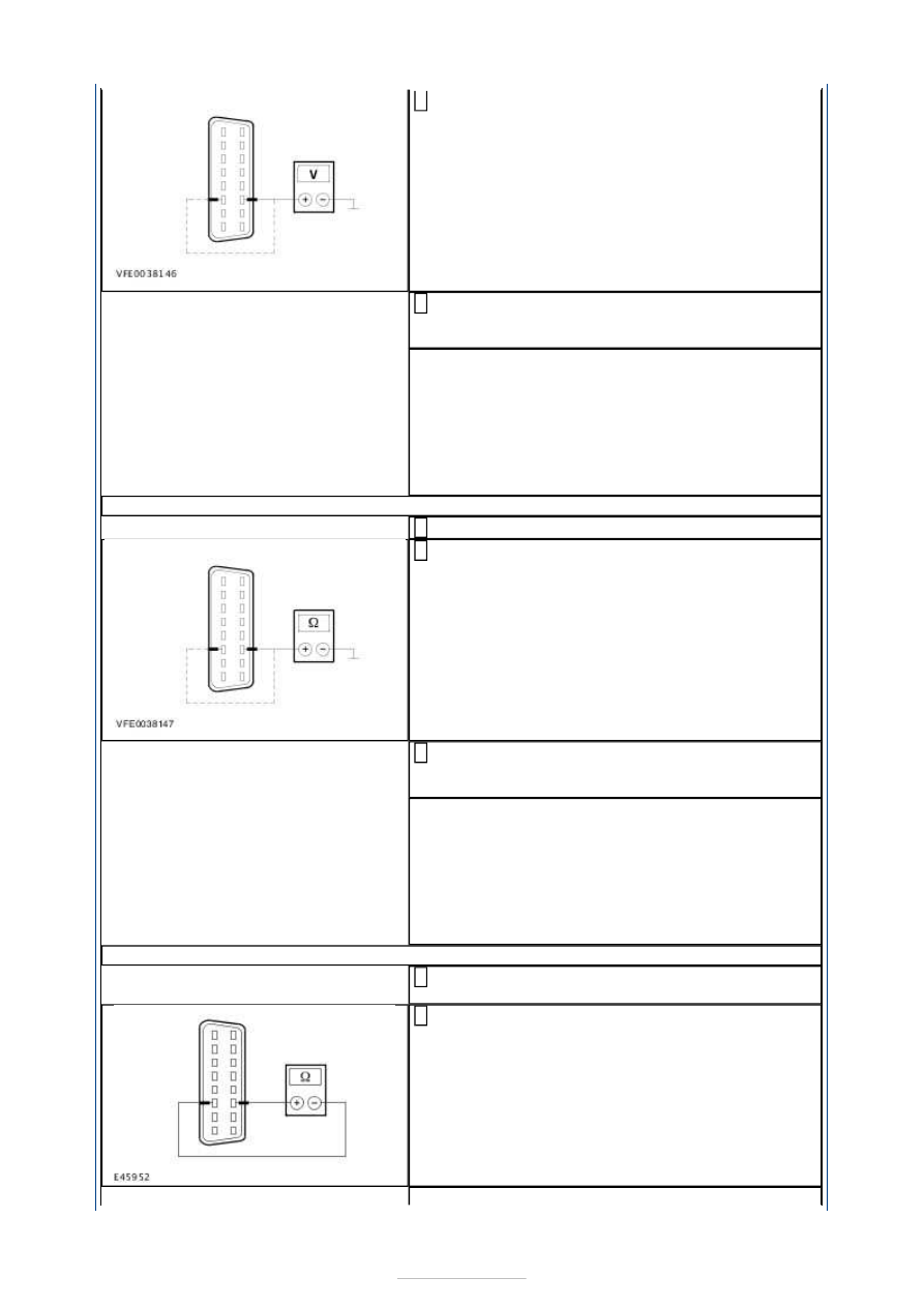
Measure the voltage between the DLC, connector 
C3DB04, pin 3, circuit VDB06X (GY/OG), wiring 

harness side and ground. 

Measure the voltage between the DLC, connector 
C3DB04, pin 11, circuit VDB07D (VT/OG), wiring 

harness side and ground. 

Is a voltage measured? 
Yes 

LOCATE and RECTIFY the short to voltage supply 
in the circuits connected to soldered connection 
SP292 using the Wiring Diagrams. CHECK the 
operation of the system. 

No 

GO to AJ11

.  

AJ11: CHECK THE MS CAN BUS FOR A SHORT TO GROUND

Ignition switch in position 0. 

Measure the resistance between the DLC, 
connector C3DB04, pin 3, circuit VDB06X 

(GY/OG), wiring harness side and ground. 

Measure the resistance between the DLC, 
connector C3DB04, pin 11, circuit VDB07D 

(VT/OG), wiring harness side and ground. 

Is a resistance of more than 10,000 Ohm measured? 
Yes 

GO to AJ12

.  

No 

LOCATE and RECTIFY the short to ground in the 
circuits connected to soldered connection SP292 
with the aid of the Wiring Diagrams. CHECK the 
operation of the system. 

AJ12: CHECK THE MS CAN BUS FOR SHORT CIRCUIT

Disconnect Connector C2MC01 from the electronic 
instrument cluster. 

Measure the resistance between the DLC, 
connector C3DB04, between pin 3, circuit VDB06X 

(GY/OG), wiring harness side and pin 11, circuit 
VDB07D (VT/OG), wiring harness side. 


Is a resistance of between 115 and 120 Ohm 
measured? 
Yes 

GO to AJ13

.  

No 

GO to AJ15

.  

AJ13: CHECK FOR OPEN CIRCUIT BETWEEN THE ELECTRONIC INSTRUMENT CLUSTER 
AND THE DATA LINK CONNECTOR (DLC)

Measure the resistance between the instrument 
cluster, connector C2MC01, pin 22, circuit 

VDB07A (VT/OG), wiring harness side and the 
DLC, connector C3DB04, pin 11, circuit VDB07D 
(VT/OG), wiring harness side. 

Is a resistance of less than 2 Ohms registered? 
Yes 

GO to AJ14

.  

No 

LOCATE and RECTIFY the break in the circuit 
between the electronic instrument cluster and the 
DLC using the Wiring Diagrams. CHECK the 
operation of the system. 

AJ14: CHECK FOR OPEN CIRCUIT BETWEEN THE ELECTRONIC INSTRUMENT CLUSTER 
AND THE DLC

Measure the resistance between the instrument 
cluster, connector C2MC01, pin 23, circuit 

VDB06A (GY/OG), wiring harness side and the 
DLC, connector C3DB04, pin 3, circuit VDB06X 
(GY/OG), wiring harness side. 

Is a resistance of less than 2 Ohms registered? 
Yes 

CHECK and if necessary RENEW the electronic 
instrument cluster. CHECK the operation of the 
system. 

No 

LOCATE and RECTIFY the break in the circuit 
between the electronic instrument cluster and the 
DLC using the Wiring Diagrams. CHECK the 
operation of the system. 

AJ15: CHECK FOR OPEN CIRCUIT BETWEEN THE GEM AND THE DLC

Disconnect Connector C1BP02-A from the GEM. 

Measure the resistance between the GEM, 
connector C1BP02-A, pin 49, circuit VDB06AC 

(GY/OG), wiring harness side and the DLC, 
connector C3DB04, pin 3, circuit VDB06X 
(GY/OG), wiring harness side. 

Is a resistance of less than 2 Ohms registered? 
Yes 

GO to AJ16

.  

No 

LOCATE and REPAIR the break in the circuit 
between the GEM and the DLC using the Wiring 
Diagrams. CHECK the operation of the system. 

AJ16: CHECK FOR OPEN CIRCUIT BETWEEN THE GEM AND THE DLC

Measure the resistance between the GEM, 
connector C1BP02-A, pin 50, circuit VDB07J 

(VT/OG), wiring harness side and the DLC, 
connector C3DB04, pin 11, circuit VDB07D 
(GY/OG), wiring harness side. 

Is a resistance of less than 2 Ohms registered? 

Yes 

TEST the GEM and RENEW as necessary. CHECK 
the operation of the system. 

No 

LOCATE and REPAIR the break in the circuit 
between the GEM and the DLC using the Wiring 
Diagrams. CHECK the operation of the system. 

AJ17: PERFORM NETWORK TEST (RESTRAINTS CONTROL MODULE (RCM))

WARNINGS: 

The backup power supply must be depleted to prevent the risk of accidental airbag 

deployment. After disconnecting the battery, wait at least 1 minute before starting work 
on the supplemental restraint system (SRS). Failure to follow this instruction may result 
in personal injury. 

In order to prevent the risk of accidental deployment, do not program any keycodes 

while working on the supplemental restraint system. Failure to follow this instruction may 
result in personal injury. 

Never use terminal probes to test any connectors of the airbag systems or of any 

other safety restraint systems. Failure to follow this instruction may result in personal 
injury. 
NOTE: After connecting the battery, initialize the power window motors. 

Disconnect Connector C2R114-A the from 
restraints control module. 

Connect ground cable from battery. 

Connect the diagnostic tool. 

Select the vehicle with the Ford approved 
diagnostic tool. 

Is it possible to establish communications with the 
GEM? 
Yes 

CHECK and if necessary RENEW the safety 
restraint control module. CHECK the operation of 
the system. 

No 

GO to AJ18

.  

AJ18: PERFORM NETWORK TEST

NOTE: The number of modules connected to the MS CAN bus depends on the equipment 
levels of the vehicle. Therefore not every vehicle will have all the modules mentioned 
below. 

Disconnect a listed component, then proceed with 
the following test step: 

Electronic automatic temperature control 
(EATC) module: C2H101 

Parking aid module: C4MP01-A 

Trailer coupling module: C4AT23-C 

Auxiliary climate control module: C3H101-A 

Fuel fired booster heater /programmable fuel 
fired booster heater: C1HF01-C 

Keyless vehicle module: C2PK28-D 

Passenger side door module: C6PL01-B 

Driver's side door module: C5PL01-B 

Electronic instrument cluster: C2MC01 

Select the vehicle with the Ford approved 
diagnostic tool. 

Is it possible to establish communications with the 
GEM? 
Yes 

The component last disconnected is the cause of 
the concern; CHECK and if necessary RENEW the 
component. CHECK the operation of the system. 

No 

- If not all the listed components are 
disconnected:DISCONNECT the next component 
(go to test step 1). 
- If all the listed components are disconnected:

GO 

to AJ19

.  

AJ19: CHECK THE MS CAN BUS FOR A SHORT TO VOLTAGE SUPPLY

Ignition switch in position 0. 

Disconnect Connector C1BP02-A from the GEM. 

Ignition switch in position II. 

Measure the voltage between the DLC, connector 
C3DB04, pin 11, circuit VDB07D (VT/OG), wiring 

harness side and ground. 

Measure the voltage between the DLC, connector 
C3DB04, pin 3, circuit VDB06X (GY/OG), wiring 

harness side and ground. 

Is a voltage measured? 
Yes 

LOCATE and RECTIFY the short to voltage supply 
in the circuits connected to soldered connection 
SP283 using the Wiring Diagrams. CHECK the 
operation of the system. 

No 

GO to AJ20

.  

AJ20: CHECK THE MS CAN BUS FOR A SHORT TO GROUND

Ignition switch in position 0. 

Measure the resistance between the DLC, 
connector C3DB04, pin 3, circuit VDB06X 

(GY/OG), wiring harness side and ground. 


Content   ..  835  836  837  838   ..