Ford Galaxy / Ford S-MAX. Manual - part 835
 

  Index      Ford     Ford Galaxy / Ford S-MAX - service repair manual 2006 year


Search            


Content   ..  833  834  835  836   ..


Ford Galaxy / Ford S-MAX. Manual - part 835


Is a resistance of less than 2 Ohms registered? 
Yes 

GO to AH13

.  

No 

LOCATE and REPAIR the break in the circuit between 
the instrument cluster and the DLC using the Wiring 
Diagrams. CHECK the operation of the system. 

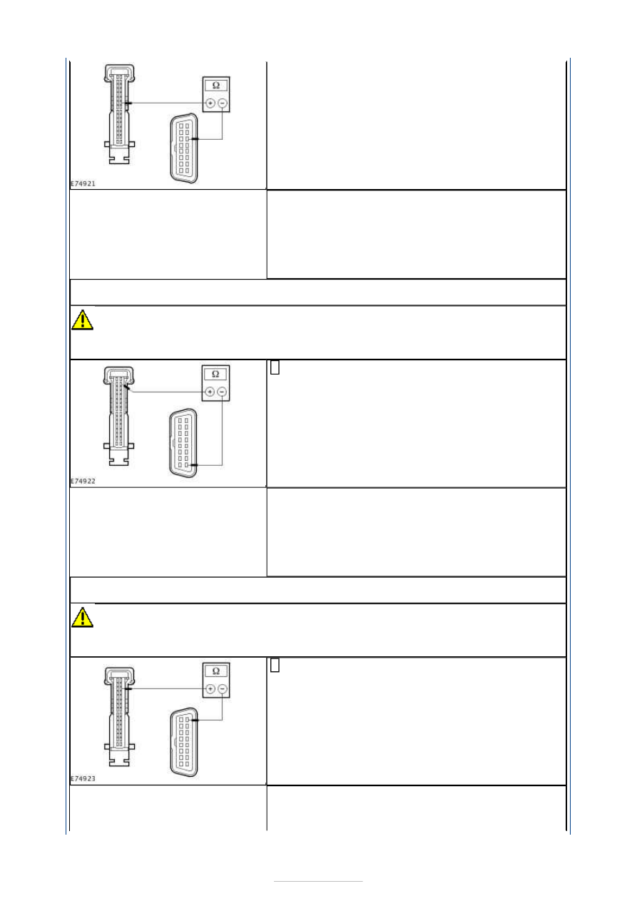
AH13: CHECK THE CIRCUIT BETWEEN THE INSTRUMENT CLUSTER AND THE DLC FOR 
OPEN CIRCUIT (MM CAN BUS)

CAUTION: The following measurement must only be performed using the Ford 

approved diagnostic tool digital multimeter. Failure to observe this instruction can lead to 
damage. 

Measure the resistance between the instrument 
cluster, connector C2MC01, pin 18, circuit VDB14X 

(VT/GY), wiring harness side and the DLC, connector 
C3DB04, pin 8, circuit VDB14F (VT/GY), wiring 
harness side. 

Is a resistance of less than 2 Ohms registered? 
Yes 

GO to AH14

.  

No 

LOCATE and REPAIR the break in the circuit between 
the instrument cluster and the DLC using the Wiring 
Diagrams. CHECK the operation of the system. 

AH14: CHECK THE CIRCUIT BETWEEN THE INSTRUMENT CLUSTER AND THE DLC FOR 
OPEN CIRCUIT (MM CAN BUS)

CAUTION: The following measurement must only be performed using the Ford 

approved diagnostic tool digital multimeter. Failure to observe this instruction can lead to 
damage. 

Measure the resistance between the instrument 
cluster, connector C2MC01, pin 19, circuit VDB13X 

(BU/GY), wiring harness side and the DLC, connector 
C3DB04, pin 1, circuit VDB13F (BU/GY), wiring 
harness side. 

Is a resistance of less than 2 Ohms registered? 
Yes 

GO to AH15

.  


No 

LOCATE and REPAIR the break in the circuit between 
the instrument cluster and the DLC using the Wiring 
Diagrams. CHECK the operation of the system. 

AH15: CHECK THE CIRCUIT BETWEEN THE INSTRUMENT CLUSTER AND THE DLC FOR 
OPEN CIRCUIT (MM CAN BUS)

CAUTION: The following measurement must only be performed using the Ford 

approved diagnostic tool digital multimeter. Failure to observe this instruction can lead to 
damage. 

Measure the resistance between the instrument 
cluster, connector C2MC01, pin 15, circuit VDB14L 

(VT/GY) (vehicles with CD changer: circuit VDB14M 
(VT/GY)), wiring harness side and the DLC, 
connector C3DB04, pin 8, circuit VDB14F (VT/GY), 
wiring harness side. 

Is a resistance of less than 2 Ohms registered? 
Yes 

GO to AH16

.  

No 

LOCATE and REPAIR the break in the circuit between 
the instrument cluster and the DLC using the Wiring 
Diagrams. CHECK the operation of the system. 

AH16: CHECK THE CIRCUIT BETWEEN THE INSTRUMENT CLUSTER AND THE DLC FOR 
OPEN CIRCUIT (MM CAN BUS)

CAUTION: The following measurement must only be performed using the Ford 

approved diagnostic tool digital multimeter. Failure to observe this instruction can lead to 
damage. 

Measure the resistance between the instrument 
cluster, connector C2MC01, pin 16, circuit VDB13L 

(BU/GY) (vehicles with CD changer: circuit VDB13M 
(BU/GY)), wiring harness side and the DLC, 
connector C3DB04, pin 1, circuit VDB14F (VT/GY), 
wiring harness side. 

Is a resistance of less than 2 Ohms registered? 
Yes 

CHECK and if necessary RENEW the instrument 
cluster. CHECK the operation of the system. 

No 

LOCATE and REPAIR the break in the circuit between 
the instrument cluster and the DLC using the Wiring 
Diagrams. CHECK the operation of the system. 

PINPOINT TEST AI : TRANSMISSION CONTROL MODULE (TCM) NOT 
COMMUNICATING WITH FORD APPROVED DIAGNOSTIC TOOL - VEHICLES 
WITH AUTOMATIC CLUTCH AND GEARSHIFT ACTUATION 

TEST 

CONDITIONS

DETAILS/RESULTS/ACTIONS

AI1: DETERMINE THE CONDITIONS UNDER WHICH THE FAULT OCCURS


Ignition switch in position 0. 

Connect the diagnostic tool. 

Select the powertrain control module (PCM) with the Ford approved 
diagnostic tool. 

Is it possible to establish communications with the PCM? 
Yes 

GO to AI2

.  

No 

GO to Pinpoint Test 

AG. 


AI2: CHECK FUSE F1

Ignition switch in position 0. 

CHECK Fuse F1 (EJB). 

Is the fuse OK? 
Yes 

GO to AI3

.  

No 

RENEW fuse F1 (10 A). CHECK the operation of the system. If the fuse 
blows again, LOCATE and REPAIR the short using the Wiring Diagrams. 

AI3: CHECK THE VOLTAGE AT FUSE F1

Connect Fuse F1 (EJB). 

Measure the voltage between fuse F1 (10 A) and ground. 

Does the meter display battery voltage? 
Yes 

GO to AI4

.  

No 

REPAIR the voltage supply to fuse F1 with the aid of the Wiring Diagrams. 
CHECK the operation of the system. 

AI4: CHECK FUSE F42

CHECK Fuse F42 (EJB). 

Is the fuse OK? 
Yes 

GO to AI5

.  

No 

RENEW fuse F42 (10 A). CHECK the operation of the system. If the fuse 
blows again, LOCATE and REPAIR the short using the Wiring Diagrams. 

AI5: CHECK THE VOLTAGE AT FUSE F42

Connect Fuse F42 (EJB). 

Ignition switch in position II. 

Measure the voltage between fuse F42 (10 A) and ground. 

Does the meter display battery voltage? 
Yes 

GO to AI6

.  

No 

REPAIR the voltage supply to fuse F42 with the aid of the Wiring Diagrams. 
CHECK the operation of the system. 

AI6: CHECK VOLTAGE AT TCM

Ignition switch in position 0. 

Disconnect Connector C1ET34 from the TCM. 

Measure the voltage between the TCM, connector C1ET34, pin 1, circuit 
CBB01A (BU), wiring harness side and ground. 

Does the meter display battery voltage? 
Yes 

GO to AI8

.  

No 

GO to AI7

.  

AI7: CHECK FOR OPEN CIRCUIT BETWEEN THE EJB AND THE TCM

Disconnect Connector C1BB03-A from the EJB. 

Measure the resistance between the EJB, connector C1BB03-A, pin 12, 
circuit CBB01A (BU), wiring harness side and the TCM, connector C1ET34, 

pin 1, circuit CBB01A (BU), wiring harness side. 

Is a resistance of less than 2 Ohms registered? 
Yes 

CHECK and if necessary RENEW the EJB. CHECK the operation of the 
system. 

No 

LOCATE and RECTIFY the break in circuit CBB01A (BU) between the TCM 
and the EJB with the aid of the Wiring Diagrams. CHECK the operation of 
the system. 

AI8: CHECK VOLTAGE AT TCM

Ignition switch in position II. 

Measure the voltage between the TCM, connector C1ET34, pin 11, circuit 
CBB42D (GN), wiring harness side and ground. 

Does the meter display battery voltage? 
Yes 

GO to AI10

.  

No 

GO to AI9

.  

AI9: CHECK FOR OPEN CIRCUIT BETWEEN THE EJB AND THE TCM

Ignition switch in position 0. 

Disconnect Connector C1BB03A from the CJB. 

Measure the resistance between the EJB, connector C1BB03A, pin 99, 
circuit CBB42B (GN), wiring harness side and the TCM, connector C1ET34, 

pin 11, circuit CBB42D (GN), wiring harness side. 

Is a resistance of less than 2 Ohms registered? 
Yes 

CHECK and if necessary RENEW the EJB. CHECK the operation of the 
system. 

No 

LOCATE and REPAIR the break in the circuit between the TCM and the EJB 
with the aid of the Wiring Diagrams. CHECK the operation of the system. 

AI10: CHECK GROUND CONNECTION OF TCM

Ignition switch in position 0. 

Measure the resistance between the TCM, connector C1ET34, pin 9, circuit 
GD120T (BK/GN) (vehicles with IS6 engine: circuit GD120V (BK/GN)), 

wiring harness side and ground. 

Is a resistance of less than 2 Ohms registered? 
Yes 

GO to AI11

.  

No 

Vehicles with DW12 engine:LOCATE and REPAIR the break in circuit 
GD120T (BK/GN) between the TCM and ground connection G1D108B with 
the aid of the Wiring Diagrams. CHECK the operation of the system. 
Vehicles with DW10 I4 engine:LOCATE and REPAIR the open circuit 
between the TCM and ground connection G1D108D using the Wiring 
Diagrams. CHECK the operation of the system. 
Vehicles with SI6 engine:LOCATE and REPAIR the break in circuit GD120V 
(BK/GN) between the TCM and ground connection G1D108B with the aid of 
the Wiring Diagrams. CHECK the operation of the system. 

AI11: CHECK FOR OPEN CIRCUIT BETWEEN THE TCM AND THE DLC.

CAUTION: The following measurement must only be performed using the Ford 

approved diagnostic tool digital multimeter. Failure to observe this instruction can lead to 
damage. 

Measure the resistance between the PTCM, connector C1ET34, pin 14, 


Content   ..  833  834  835  836   ..