Ford Galaxy / Ford S-MAX. Manual - part 796
 

  Index      Ford     Ford Galaxy / Ford S-MAX - service repair manual 2006 year


Search            


Content   ..  794  795  796  797   ..


Ford Galaxy / Ford S-MAX. Manual - part 796


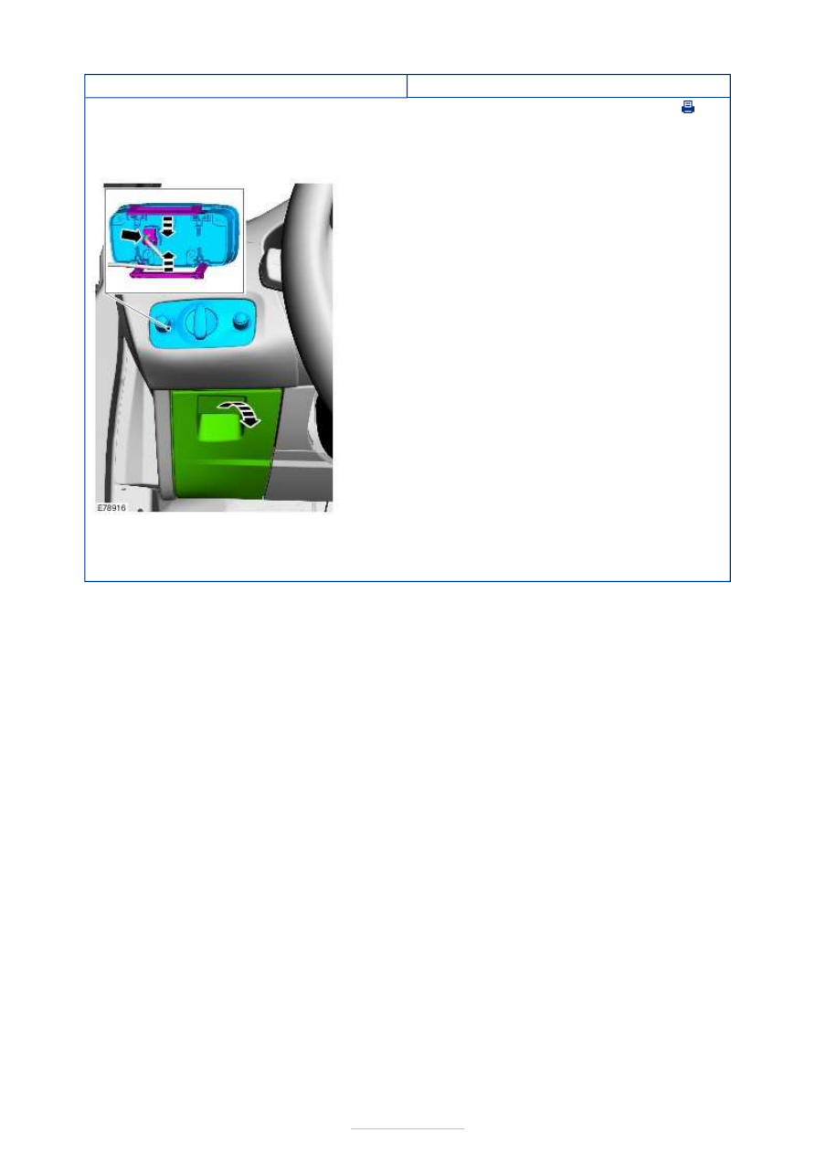
Exterior Lighting - Headlamp Switch

S-MAX/Galaxy 2006.5 (02/2006-)


Print


Removal and Installation 

Removal 

Installation 

1.  

1. Install the components in reverse order. 


Exterior Lighting - Headlamp Leveling 
Front Sensor

S-MAX/Galaxy 2006.5 (02/2006-)


Print


Removal and Installation 

Removal 

NOTE: Removal steps in this procedure may contain installation details. 

Installation 

1. Raise the vehicle. 

Refer to: 

Lifting

 (100-02 Jacking and Lifting, 

Description and Operation). 

2.   

1. Torque: 8 Nm 
2. Torque: 10 Nm 

1. To install, reverse the removal procedure. 

2. Following installation of the front headlamp 

leveling sensor, calibrate the headlamp leveling 
system using WDS. 

3. Check the aim of the dip beam headlamps. 

Refer to: 

Headlamp Adjustment

 (417-01 Exterior 

Lighting, General Procedures). 


Exterior Lighting - Headlamp Leveling 
Rear Sensor

S-MAX/Galaxy 2006.5 (02/2006-)


Print


Removal and Installation 

Removal 

NOTE: Removal steps in this procedure may contain installation details. 

Installation 

1. Raise the vehicle. 

Refer to: 

Lifting

 (100-02 Jacking and Lifting, 

Description and Operation). 

2. Torque: 10 Nm 

1. To install, reverse the removal procedure. 

2. Following installation of the rear headlamp 

leveling sensor, calibrate the headlamp leveling 
system using WDS. 

3. Check the aim of the dip beam headlamps. 

Refer to: 

Headlamp Adjustment

 (417-01 Exterior 

Lighting, General Procedures). 


Interior Lighting - Interior Lighting

S-MAX/Galaxy 2006.5 (02/2006-)


Print


Diagnosis and Testing 

Refer to Wiring Diagrams Section 417-02, for schematic and connector 
information.  

General Equipment 

Inspection and Verification 

1. 1. Verify the customer concern. 

2. 2. Visually inspect for obvious signs of electrical damage. 

Visual Inspection Chart 

3. 3. If an obvious cause for an observed or reported concern is found, correct the cause 

(if possible) before proceeding to the next step. 

4. 4. If the cause is not visually evident, verify the symptom and refer to the Symptom 

Chart. 

Symptom Chart 

Worldwide Diagnostic System (WDS)

Electrical

Bulb(s)  
Fuse(s)  
Switch(es)  
Wiring harness  
Electrical connector(s)  
Interior lamp(s)  
Battery saver relay  
Central junction box (CJB) 

Symptom

Possible Sources

Action

The front interior lamp is inoperative

Fuse(s). 
Bulb(s). 
Circuit(s). 
Front interior lamp. 
Battery saver relay. 
CJB. 

*
*
*
*
*
*

GO to Pinpoint 

Test 

A. 


*

The middle interior lamp is inoperative

Fuse(s). 
Bulb(s). 
Circuit(s). 
Middle interior lamp. 
Battery saver relay. 
CJB. 

*
*
*
*
*
*

GO to Pinpoint 

Test 

B. 


*

The rear interior lamp is inoperative

Fuse(s). 
Bulb(s). 
Circuit(s). 
Rear interior lamp. 
Battery saver relay. 
CJB. 

*
*
*
*
*
*

GO to Pinpoint 

Test 

C. 


*

The luggage compartment lamp is inoperative

Fuse(s). 
Bulb(s). 
Circuit(s). 
Luggage compartment 

*
*
*
*

GO to Pinpoint 

Test 

D. 


*


Content   ..  794  795  796  797   ..