Ford Galaxy / Ford S-MAX. Manual - part 782
 

  Index      Ford     Ford Galaxy / Ford S-MAX - service repair manual 2006 year


Search            


Content   ..  780  781  782  783   ..


Ford Galaxy / Ford S-MAX. Manual - part 782


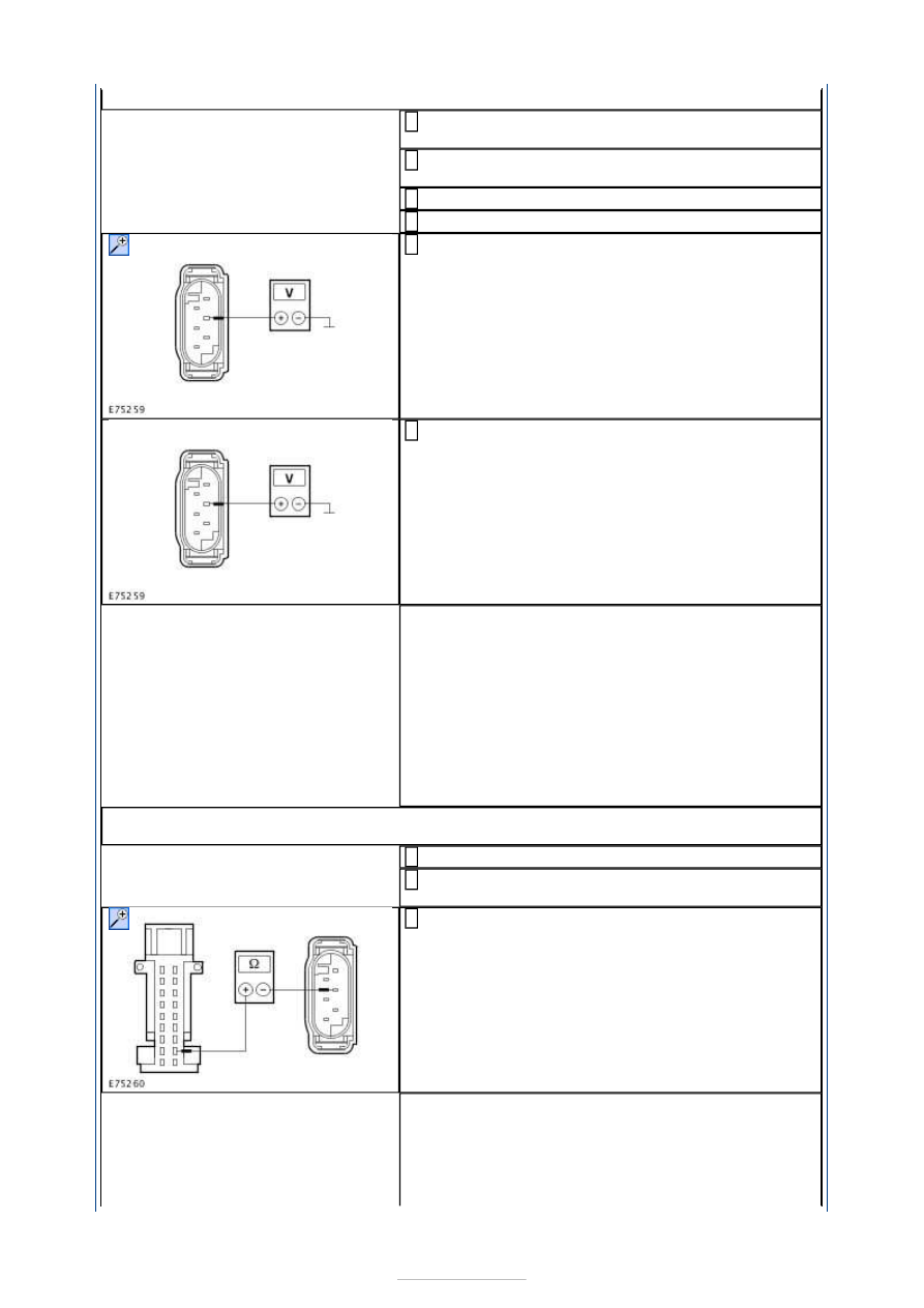
OPEN CIRCUIT

Connect Adaptive front lighting module to 
connector C2LF23A. 

Connect Adaptive front lighting module to 
connector C2LF23B. 

Ignition switch in position II. 

SWITCH ON dipped beam. 

Measure the voltage between front headlamp 
levelling sensor, connector C5CD07, pin 5, circuit 

LCD23B (GN/OG), wiring harness side and ground. 

Measure the voltage between rear headlamp 
levelling sensor, connector C7CD12, pin 5, circuit 

LCD23D (GN/OG), wiring harness side and ground. 

Is a voltage of 5 Volts measured in both cases? 
Yes 

GO to B17

.  

No 

- If no voltage is measured during both of the 
measurements: 

GO to B16

.  

- Is a voltage of 5 Volts measured during just one 
measurement? LOCATE and RECTIFY break in the 
affected circuit between soldered connection SP406 
and headlamp levelling sensor using the Wiring 
Diagrams. CHECK the operation of the system. 

B16: RULE OUT THE ADAPTIVE FRONT LIGHTING MODULE AS A POSSIBLE CAUSE OF 
THE FAULT

Ignition switch in position 0. 

Disconnect Adaptive front lighting module from 
connector C2LF23A. 

Measure the resistance between adaptive front 
lighting module, connector C2LF23A, pin 11, circuit 

LCD23G (GN/OG), wiring harness side and front 
headlamp levelling sensor, connector C5CD07, pin 
5, circuit LCD23B (GN/OG), wiring harness side. 

Is a resistance of less than 2 Ohms registered? 
Yes 

RENEW the adaptive front lighting module. CHECK 
the operation of the system. 

No 

LOCATE and RECTIFY break in circuit between 


adaptive front lighting module and soldered 
connection SP406 using the Wiring Diagrams. 
CHECK the operation of the system. 

B17: RULE OUT THE ADAPTIVE FRONT LIGHTING MODULE AS A POSSIBLE CAUSE OF 
THE FAULT

Ignition switch in position II. 

Measure the resistance between front headlamp 
levelling sensor, connector C5CD07, pin 1, circuit 

RCD02G (GN/BN), wiring harness side and ground. 

Measure the resistance between rear headlamp 
levelling sensor, connector C7CD12, pin 1, circuit 

RCD23D (WH/BN), wiring harness side and ground. 

Is a resistance of less than 2 Ohm measured in both 
cases? 
Yes 

GO to B19

.  

No 

- If a resistance of less than 2 Ohm is not 
measured in either measurement: RENEW the 
adaptive front lighting module. CHECK the 
operation of the system. 
- If a resistance of less than 2 Ohm is measured in 
one measurement: 

GO to B18

.  

B18: RULE OUT THE ADAPTIVE FRONT LIGHTING MODULE AS A POSSIBLE CAUSE OF 
THE FAULT

Ignition switch in position 0. 

Disconnect Adaptive front lighting module from 
connector C2LF23A. 

Open circuit in ground connection to front 
headlamp levelling sensor: Measure the resistance 

between adaptive front lighting module, connector 
C2LF23A, pin 12, circuit RCD02L (GN/BN), wiring 
harness side and front headlamp levelling sensor, 
connector C5CD07, pin 1, circuit RCD02G (GN/BN), 
wiring harness side. 

Open circuit in ground connection to rear headlamp 
levelling sensor: Measure the resistance between 

adaptive front lighting module, connector C2LF23A, 
pin 3, circuit RCD23K (WH/BN), wiring harness side 
and rear headlamp levelling sensor, connector 
C7CD12, pin 1, circuit RCD23D (WH/BN), wiring 
harness side. 


Is a resistance of less than 2 Ohms registered? 
Yes 

RENEW the adaptive front lighting module. CHECK 
the operation of the system. 

No 

LOCATE and RECTIFY break in circuit between 
adaptive front lighting module and headlamp 
levelling sensor using the Wiring Diagrams. CHECK 
the operation of the system. 

B19: CHECK SIGNAL CIRCUIT BETWEEN ADAPTIVE FRONT LIGHTING MODULE AND 
FRONT HEADLAMP LEVELLING SENSOR FOR SHORT CIRCUIT TO BATTERY VOLTAGE

Ignition switch in position II. 

Measure the voltage between front headlamp 
levelling sensor, connector C5CD07, pin 4, circuit 

VCD10B (BN), wiring harness side and ground. 

Does the meter display battery voltage? 
Yes 

LOCATE and RECTIFY the short to battery voltage 
in circuit(s) between adaptive front lighting module 
and headlamp levelling sensor using the Wiring 
Diagrams. CHECK the operation of the system. 

No 

GO to B20

.  

B20: CHECK SIGNAL CIRCUIT BETWEEN ADAPTIVE FRONT LIGHTING MODULE AND 
FRONT HEADLAMP LEVELLING SENSOR FOR SHORT CIRCUIT TO GROUND

Ignition switch in position 0. 

Measure the resistance between front headlamp 
levelling sensor, connector C5CD07, pin 4, circuit 

VCD10B (BN), wiring harness side and ground. 

Is a resistance of more than 10,000 Ohm measured? 
Yes 

GO to B21

.  

No 

LOCATE and RECTIFY the short to ground in circuit
(s) between adaptive front lighting module and 


headlamp levelling sensor using the Wiring 
Diagrams. CHECK the operation of the system. 

B21: CHECK SIGNAL CIRCUIT BETWEEN ADAPTIVE FRONT LIGHTING MODULE AND 
FRONT HEADLAMP LEVELLING SENSOR FOR OPEN CIRCUIT

Measure the resistance between the front 
headlamp levelling sensor, connector C5CD07, pin 

4, circuit VCD10B (BN), wiring harness side and 
adaptive front lighting module, connector C2LF23A, 
pin 15, circuit VCD10D (BN), wiring harness side. 

Is a resistance of less than 2 Ohms registered? 
Yes 

GO to B22

.  

No 

LOCATE and RECTIFY break in circuit(s) between 
adaptive front lighting module and headlamp 
levelling sensor using the Wiring Diagrams. CHECK 
the operation of the system. 

B22: CHECK SIGNAL CIRCUIT BETWEEN ADAPTIVE FRONT LIGHTING MODULE AND 
REAR HEADLAMP LEVELLING SENSOR FOR SHORT CIRCUIT TO BATTERY VOLTAGE

Ignition switch in position II. 

Measure the voltage between rear headlamp 
levelling sensor, connector C7CD12, pin 4, circuit 

VCD12B (VT/WH), wiring harness side and ground. 

Does the meter display battery voltage? 
Yes 

LOCATE and RECTIFY the short to battery voltage 
in circuit(s) between adaptive front lighting module 
and headlamp levelling sensor using the Wiring 
Diagrams. CHECK the operation of the system. 

No 

GO to B23

.  

B23: CHECK SIGNAL CIRCUIT BETWEEN ADAPTIVE FRONT LIGHTING MODULE AND 
REAR HEADLAMP LEVELLING SENSOR FOR SHORT CIRCUIT TO GROUND

Measure the resistance between rear headlamp 
levelling sensor, connector C7CD12, pin 4, circuit 

VCD12B (VT/WH), wiring harness side and ground. 

Is a resistance of more than 10,000 Ohm measured? 
Yes 

GO to B24

.  

No 


Content   ..  780  781  782  783   ..