Ford Galaxy / Ford S-MAX. Manual - part 780
 

  Index      Ford     Ford Galaxy / Ford S-MAX - service repair manual 2006 year


Search            


Content   ..  778  779  780  781   ..


Ford Galaxy / Ford S-MAX. Manual - part 780


cases? 
Yes 

GO to A16

.  

No 

LOCATE and REPAIR the break in the affected 
circuit using the Wiring Diagrams. CHECK the 
operation of the system. 

A15: CHECK COMMON CONTROL CIRCUIT OF HEADLAMP LEVELLING FOR OPEN 
CIRCUIT

Measure the resistance between adaptive front 
lighting module, connector C2LF23D, pin 4, circuit 

VLF22B (VT/GN), wiring harness side and left-hand 
headlamp, connector C1LF08, pin 3, circuit VLF22A 
(VT/GN), wiring harness side. 

Is a resistance of less than 2 Ohms registered? 
Yes 

GO to A16

.  

No 

LOCATE and RECTIFY break in circuit between 
lighting control module and intermediate connector 
C21A/B using the Wiring Diagrams. CHECK the 
operation of the system. 

A16: RULE OUT THE LEFT-HAND HEADLAMP AS A POSSIBLE CAUSE OF THE FAULT

Connect Left-hand headlamp to connector 
C1LF08A. 

Ignition switch in position II. 

Vehicles without adaptive front lighting module: 
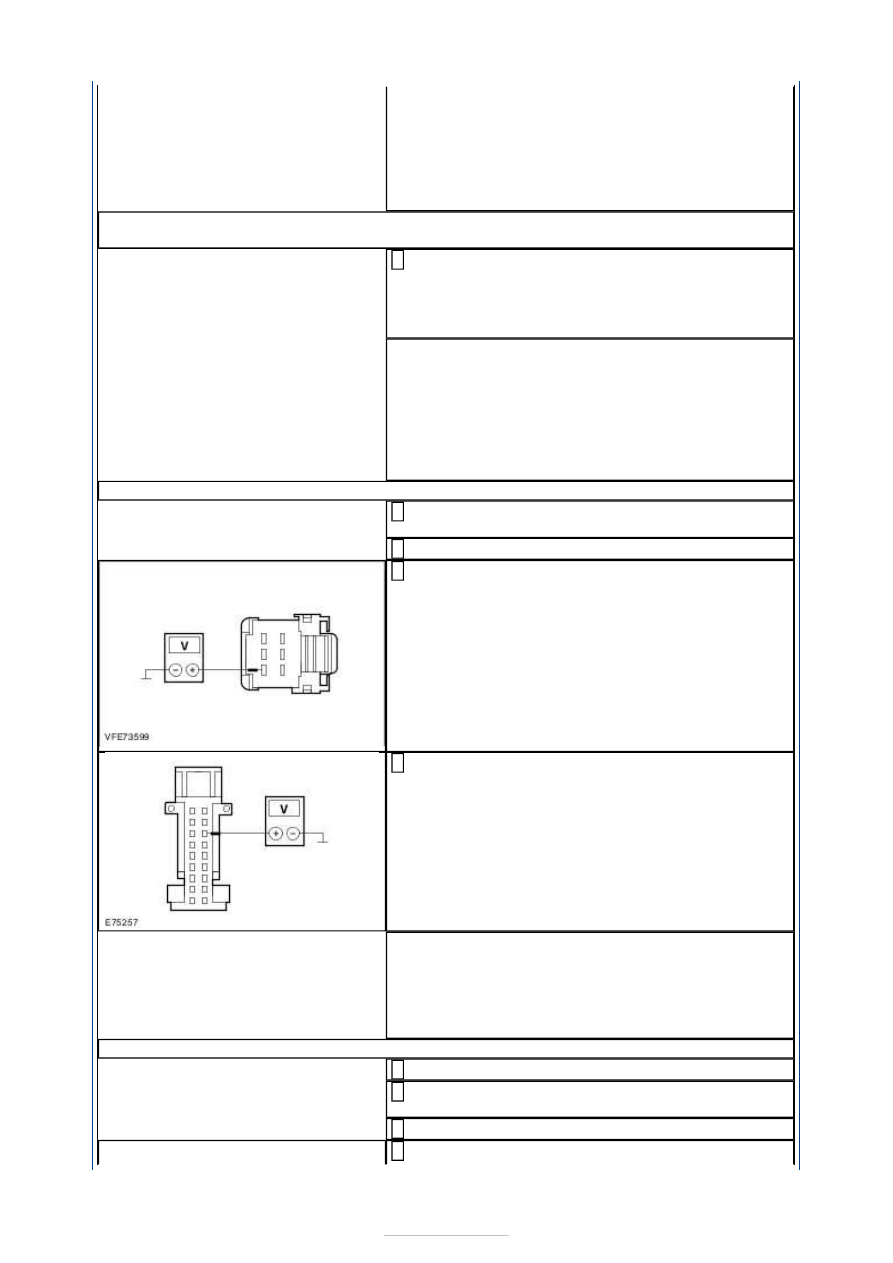
Measure the voltage between adaptive front 

lighting module, connector C2LF23D, pin 4, circuit 
VLF22B (VT/GN), wiring harness side and ground. 

Vehicles with adaptive front lighting module: 
Measure the voltage between adaptive front 

lighting module, connector C2LF23A, pin 16, circuit 
VLF22E (VT/GN), wiring harness side and ground. 

Does the meter display battery voltage? 
Yes 

RENEW left-hand headlamp. CHECK the operation 
of the system. 

No 

GO to A17

.  

A17: RULE OUT THE RIGHT-HAND HEADLAMP AS A POSSIBLE CAUSE OF THE FAULT

Ignition switch in position 0. 

Connect Right-hand headlamp to connector 
C1LF09. 

Ignition switch in position II. 

Vehicles without adaptive front lighting module: 


Measure the voltage between adaptive front 
lighting module, connector C2LF23D, pin 4, circuit 
VLF22B (VT/GN), wiring harness side and ground. 

Vehicles with adaptive front lighting module: 
Measure the voltage between adaptive front 

lighting module, connector C2LF23A, pin 16, circuit 
VLF22E (VT/GN), wiring harness side and ground. 

Does the meter display battery voltage? 
Yes 

RENEW right-hand headlamp. CHECK the operation 
of the system. 

No 

- vehicles without adaptive front lighting module: 
RENEW lighting control module. CHECK the 
operation of the system. 
- vehicles with adaptive front lighting module: 

GO 

to A18

.  

A18: RULE OUT THE LIGHTING CONTROL MODULE AS A POSSIBLE SOURCE OF THE 
FAULT.

Ignition switch in position 0. 

Connect Lighting control module to connector 
C2LF23D. 

Ignition switch in position II. 

SWITCH ON dipped beam. 

OPERATE the headlamp levelling (UP/DOWN). 

Measure the voltage between adaptive front 
lighting module, connector C2LF23A, pin 9, circuit 

A_VLF22A (VT/GN), wiring harness side and 
ground. 

Does the voltage measurement change in line with the 
headlamp levelling position. 
Yes 

RENEW adaptive front lighting module. CHECK the 
operation of the system. 

No 

RENEW lighting control module. CHECK the 
operation of the system. 

A19: CHECK VOLTAGE SUPPLY OF LEFT-HAND HEADLAMP LEVELLING MOTOR FOR 
OPEN CIRCUIT


Ignition switch in position 0. 

Disconnect Left-hand headlamp from connector 
C1LF08. 

Ignition switch in position II. 

SWITCH ON dipped beam. 

Measure the voltage between left-hand headlamp, 
connector C1LF08, pin 1, circuit CBB43B (GY), 

wiring harness side and ground. 

Does the meter display battery voltage? 
Yes 

GO to A20

.  

No 

LOCATE and RECTIFY the break in the circuit 
between soldered connection SP171 and headlamp 
using the Wiring Diagrams. CHECK the operation of 
the system. 

A20: CHECK GROUND CONNECTION OF LEFT-HAND HEADLAMP LEVELLING MOTOR 
FOR OPEN CIRCUIT

Ignition switch in position 0. 

Measure the resistance between the left-hand 
headlamp, connector C1LF08, pin 11, circuit 

GD130AE (BK/YE), wiring harness side and ground. 

Is a resistance of less than 2 Ohms registered? 
Yes 

GO to A21

.  

No 

LOCATE and RECTIFY the break in the circuit 
between the headlamp and soldered connection 
SP371 using the Wiring Diagrams. CHECK the 
operation of the system. 

A21: CHECK CONTROL CIRCUIT OF LEFT-HAND HEADLAMP LEVELLING MOTOR FOR 
OPEN CIRCUIT

Disconnect Right-hand headlamp from connector 
C1LF09. 

Measure the resistance between left-hand 
headlamp, connector C1LF08, pin 3, circuit VLF22A 

(VT/GN), wiring harness side and right-hand 
headlamp, connector C1LF09, pin 3, circuit VLF22C 
(VT/GN), wiring harness side. 

Is a resistance of less than 2 Ohms registered? 
Yes 

RENEW left-hand headlamp. CHECK the operation 
of the system. 

No 

LOCATE and RECTIFY break in circuit between 
headlamp and intermediate connector C21A/B 
using the Wiring Diagrams. CHECK the operation of 
the system. 

A22: CHECK VOLTAGE SUPPLY OF RIGHT-HAND HEADLAMP LEVELLING MOTOR FOR 
OPEN CIRCUIT

Ignition switch in position 0. 

Disconnect Right-hand headlamp from connector 
C1LF09. 

Ignition switch in position II. 

SWITCH ON dipped beam. 

Measure the voltage between right-hand 
headlamp, connector C1LF09, pin 1, circuit CBB43A 

(GY), wiring harness side and ground. 

Does the meter display battery voltage? 
Yes 

GO to A23

.  

No 

LOCATE and RECTIFY the break in the circuit 
between soldered connection SP171 and headlamp 
using the Wiring Diagrams. CHECK the operation of 
the system. 

A23: CHECK GROUND CONNECTION OF RIGHT-HAND HEADLAMP LEVELLING MOTOR 
FOR OPEN CIRCUIT

Ignition switch in position 0. 

Measure the resistance between the right-hand 
headlamp, connector C1LF09, pin 11, circuit 

GD132W (BK/VT), wiring harness side and ground. 

Is a resistance of less than 2 Ohms registered? 
Yes 

GO to A24

.  

No 

LOCATE and RECTIFY the break in the circuit 
between the headlamp and soldered connection 
SP380 using the Wiring Diagrams. CHECK the 
operation of the system. 

A24: CHECK CONTROL CIRCUIT OF RIGHT-HAND HEADLAMP LEVELLING MOTOR FOR 
OPEN CIRCUIT

Disconnect Left-hand headlamp from connector 
C1LF08. 

Measure the resistance between left-hand 
headlamp, connector C1LF08, pin 3, circuit VLF22A 

(VT/GN), wiring harness side and right-hand 
headlamp, connector C1LF09, pin 3, circuit VLF22C 
(VT/GN), wiring harness side. 

Is a resistance of less than 2 Ohms registered? 
Yes 

RENEW headlamp. CHECK the operation of the 
system. 

No 

LOCATE and RECTIFY break in circuit between 
headlamp and intermediate connector C21A/B 
using the Wiring Diagrams. CHECK the operation of 
the system. 

PINPOINT TEST B : THE HEADLAMP LEVELLING IS INOPERATIVE/DOES 
NOT OPERATE CORRECTLY (VEHICLES WITH XENON HEADLAMPS) 

WARNING: High voltages of up to 30 kV are present in the system. Ensure that the 

headlamp assembly electrical connector is disconnected if the headlamp assembly is 
removed. 
NOTE: It is not possible to adjust the headlamps manually. 
NOTE: For testing the basic function of the automatic headlamp levelling system, switch 
on the dipped beams and change the load (rear axle) of the vehicle. Check if the 
headlamp levelling system adjusts the headlamps correctly. 
NOTE: The headlamp levelling positioning motor cannot be replaced by itself. If 
necessary, it needs to be replaced together with the complete headlamp unit. 

TEST CONDITIONS

DETAILS/RESULTS/ACTIONS

B1: DETERMINE THE CAUSE OF THE FAULT

Ignition switch in position II. 

SWITCH ON dipped beams. 

CHECK the headlamp levelling. 


Content   ..  778  779  780  781   ..