Ford Galaxy / Ford S-MAX. Manual - part 783
 

  Index      Ford     Ford Galaxy / Ford S-MAX - service repair manual 2006 year


Search            


Content   ..  781  782  783  784   ..


Ford Galaxy / Ford S-MAX. Manual - part 783


LOCATE and RECTIFY the short to ground in circuit
(s) between adaptive front lighting module and 
headlamp levelling sensor using the Wiring 
Diagrams. CHECK the operation of the system. 

B24: CHECK SIGNAL CIRCUIT BETWEEN ADAPTIVE FRONT LIGHTING MODULE AND 
REAR HEADLAMP LEVELLING SENSOR FOR OPEN CIRCUIT

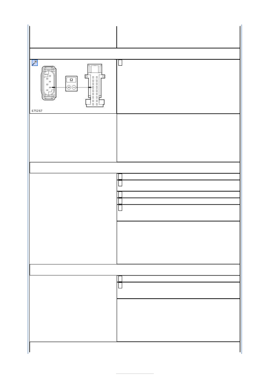
Measure the resistance between the rear headlamp 
levelling sensor, connector C7CD12, pin 4, circuit 

VCD12B (VT/WH), wiring harness side and adaptive 
front lighting module, connector C2LF23A, pin 6, 
circuit VCD12C (VT/WH), wiring harness side. 

Is a resistance of less than 2 Ohms registered? 
Yes 

RENEW the adaptive front lighting module. CHECK 
the operation of the system. 

No 

LOCATE and RECTIFY break in circuit(s) between 
adaptive front lighting module and headlamp 
levelling sensor using the Wiring Diagrams. CHECK 
the operation of the system. 

B25: CHECK VOLTAGE SUPPLY OF LEFT-HAND HEADLAMP LEVELLING MOTOR FOR 
OPEN CIRCUIT

Ignition switch in position 0. 

Disconnect Left-hand headlamp from connector 
C1LF08. 

Ignition switch in position II. 

SWITCH ON dipped beam. 

Measure the voltage between left-hand headlamp, 
connector C1LF08, pin 13, circuit CBB39E 

(VT/WH), wiring harness side and ground. 

Does the meter display battery voltage? 
Yes 

GO to B26

.  

No 

LOCATE and RECTIFY break in circuit between 
soldered connection SP172 and headlamp using the 
Wiring Diagrams. CHECK the operation of the 
system. 

B26: CHECK GROUND CONNECTION OF LEFT-HAND HEADLAMP LEVELLING MOTOR 
FOR OPEN CIRCUIT

Ignition switch in position 0. 

Measure the resistance between the left-hand 
headlamp, connector C1LF08, pin 11, circuit 

GD130AE (BK/YE), wiring harness side and ground. 

Is a resistance of less than 2 Ohms registered? 
Yes 

GO to B27

.  

No 

LOCATE and RECTIFY the break in the circuit 
between the headlamp and soldered connection 
SP371 using the Wiring Diagrams. CHECK the 
operation of the system. 

B27: CHECK LIN DATABUS CONNECTION BETWEEN ADAPTIVE FRONT LIGHTING 


MODULE AND LEFT-HAND HEADLAMP FOR OPEN CIRCUIT

Disconnect Right-hand headlamp from connector 
C1LF09. 

Measure resistance between left-hand headlamp, 
connector C1LF08, pin 14, circuit VLF32A (YE), 

wiring harness side and right-hand headlamp, 
connector C1LF09, pin 14, circuit VLF32C (YE), 
wiring harness side. 

Is a resistance of less than 2 Ohms registered? 
Yes 

CHECK headlamp levelling motor. CHECK the 
operation of the system. If the concern persists, 
RENEW the headlamp. CHECK the operation of the 
system. 

No 

LOCATE and RECTIFY break in circuit between left-
hand headlamp and intermediate connector C21A/B 
using the Wiring Diagrams. CHECK the operation of 
the system. 

B28: CHECK VOLTAGE SUPPLY OF RIGHT-HAND HEADLAMP LEVELLING MOTOR FOR 
OPEN CIRCUIT

Ignition switch in position 0. 

Disconnect Right-hand headlamp from connector 
C1LF09. 

Ignition switch in position II. 

SWITCH ON dipped beam. 

Measure the voltage between right-hand 
headlamp, connector C1LF09, pin 13, circuit 

CBB39F (VT/WH), wiring harness side and ground. 

Does the meter display battery voltage? 
Yes 

GO to B29

.  

No 

LOCATE and RECTIFY break in circuit between 
soldered connection SP172 and headlamp using the 
Wiring Diagrams. CHECK the operation of the 
system. 

B29: CHECK GROUND CONNECTION OF RIGHT-HAND HEADLAMP LEVELLING MOTOR 
FOR OPEN CIRCUIT

Ignition switch in position 0. 

Measure the resistance between the right-hand 
headlamp, connector C1LF09, pin 11, circuit 

GD132W (BK/VT), wiring harness side and ground. 

Is a resistance of less than 2 Ohms registered? 
Yes 

GO to B30

.  

No 

LOCATE and RECTIFY the break in the circuit 
between the headlamp and soldered connection 
SP380 using the Wiring Diagrams. CHECK the 
operation of the system. 

B30: CHECK THE LIN DATABUS CONNECTION FOR OPEN CIRCUIT

Disconnect Left-hand headlamp from connector 
C1LF08. 

Measure resistance between left-hand headlamp, 
connector C1LF08, pin 14, circuit VLF32A (YE), 

wiring harness side and right-hand headlamp, 
connector C1LF09, pin 14, circuit VLF32C (YE), 

Component checks 

HEADLAMP LEVELLING SENSOR 

CAUTIONS: 

Electronic modules are sensitive to electrical charge. If exposed to these charges, 

damage may result. 

Be sure, that the headlamp levelling sensor is supplied with exactly 5 volts. 

NOTE: Check the headlamp levelling sensor when installed. 

Switch off the ignition.  
Disconnect the electrical connector.  
Using an external 5 volts DC supply.  
Using a digital multimeter.  
Using a test cable, set up the test as in the following description. 

1. 1. Check headlamp levelling sensor, front/rear. 

Connect the positive terminal of the voltage supply with fused cable (5 A) to pin 5 of the 
headlamp levelling sensor and the negative terminal to pin 1.  
To measure the voltage at the sensor, connect the positive terminal of the Digital 
Multimeter to pin 4 and the negative terminal to pin 1.  
Change the vehicle load during the measurement. 

Measure the voltage. 

Is the range of values at the digital multimeter between 2.0 - 2.7 volts? 

If yes, the headlamp levelling sensor is OK. 

If no, RENEW the headlamp levelling sensor. 

wiring harness side. 

Is a resistance of less than 2 Ohms registered? 
Yes 

CHECK headlamp levelling motor. CHECK the 
operation of the system. If the concern persists, 
RENEW the headlamp. CHECK the operation of the 
system. 

No 

LOCATE and RECTIFY break in circuit between 
right-hand headlamp and intermediate connector 
C21A/B using the Wiring Diagrams. CHECK the 
operation of the system. 


Exterior Lighting - Parking, Rear and 
License Plate Lamps

S-MAX/Galaxy 2006.5 (02/2006-)


Print


Diagnosis and Testing 

Refer to Wiring Diagrams Section 417-01, for schematic and connector 
information.  

Special Tool(s) 

Inspection and Testing 

NOTE: The generic electronic module (GEM) is part of the central junction box (CJB). 
NOTE: A new GEM needs to be configured after installation. For this purpose, the vehicle-
specific data are read out of the module to be changed using WDS and is transferred to 
the new module. REFER to:  

Module Configuration

 (418-01 Module Configuration, General Procedures), 

Generic Electronic Module (GEM)

 (419-10 Multifunction Electronic Modules, Diagnosis and 

Testing). 

NOTE: Before reading out the vehicle-specific data make sure that all electrical 
connections in the vehicle are reconnected so that the module and WDS can communicate 
correctly. 

1. 1. Verify the customer concern. 

2. 2. Visually inspect for obvious signs of electrical damage. 

Visual Inspection Chart 

3. 3. Resolve any obvious causes or concerns found during the visual inspection before 

carrying out any further tests. 

4. 4. If the cause of the concern cannot be found by visual inspection, continue with the 

symptom chart. 

Symptom chart 

Symptom chart 

Terminal Probe Kit 

29-011A 

Electrical

Fuse(s)  
Bulb(s)  
Connector  
Switch  
Wiring loom 

Symptom

Possible Sources

Action

All parking lamps inoperative

Fuse(s) 
Circuit(s) 
Ignition switch 
LCM (Lights Control 

Module) 

Central Junction Box 

(CJB) 

*
*
*
*

*

GO to Pinpoint 

Test 

A. 


*


Content   ..  781  782  783  784   ..