Ford Galaxy / Ford S-MAX. Manual - part 765
Exterior Lighting - Stoplamps
S-MAX/Galaxy 2006.5 (02/2006-)
Diagnosis and Testing
Refer to Wiring Diagrams Section 417-01, for schematic and connector
information.
Special Tool(s)
Inspection and Testing
NOTE: The generic electronic module (GEM) is part of the central junction box (CJB).
NOTE: A new GEM needs to be configured after installation. For this purpose, the vehicle-
specific data are read out of the module to be changed using WDS and is transferred to
the new module. REFER to:
Module Configuration
(418-01 Module Configuration, General Procedures),
Generic Electronic Module (GEM)
(419-10 Multifunction Electronic Modules, Diagnosis and
Testing).
NOTE: A new PCM needs to be configured after installation. For this purpose, the vehicle-
specific data are read out of the module to be changed using WDS and is transferred to
the new module.
REFER to:
Module Configuration
(418-01 Module Configuration, General Procedures).
NOTE: Before reading out the vehicle-specific data make sure that all electrical
connections in the vehicle are reconnected so that the module and WDS can communicate
correctly.
1. 1. Verify the customer concern.
2. 2. Visually inspect for obvious signs of electrical (or mechanical) damage.
Visual Inspection Chart
3. 3. Resolve any obvious causes or concerns found during the visual inspection before
carrying out any further tests.
4. 4. If the cause of the concern cannot be found by visual inspection, continue with the
symptom chart.
Symptom chart
Symptom chart
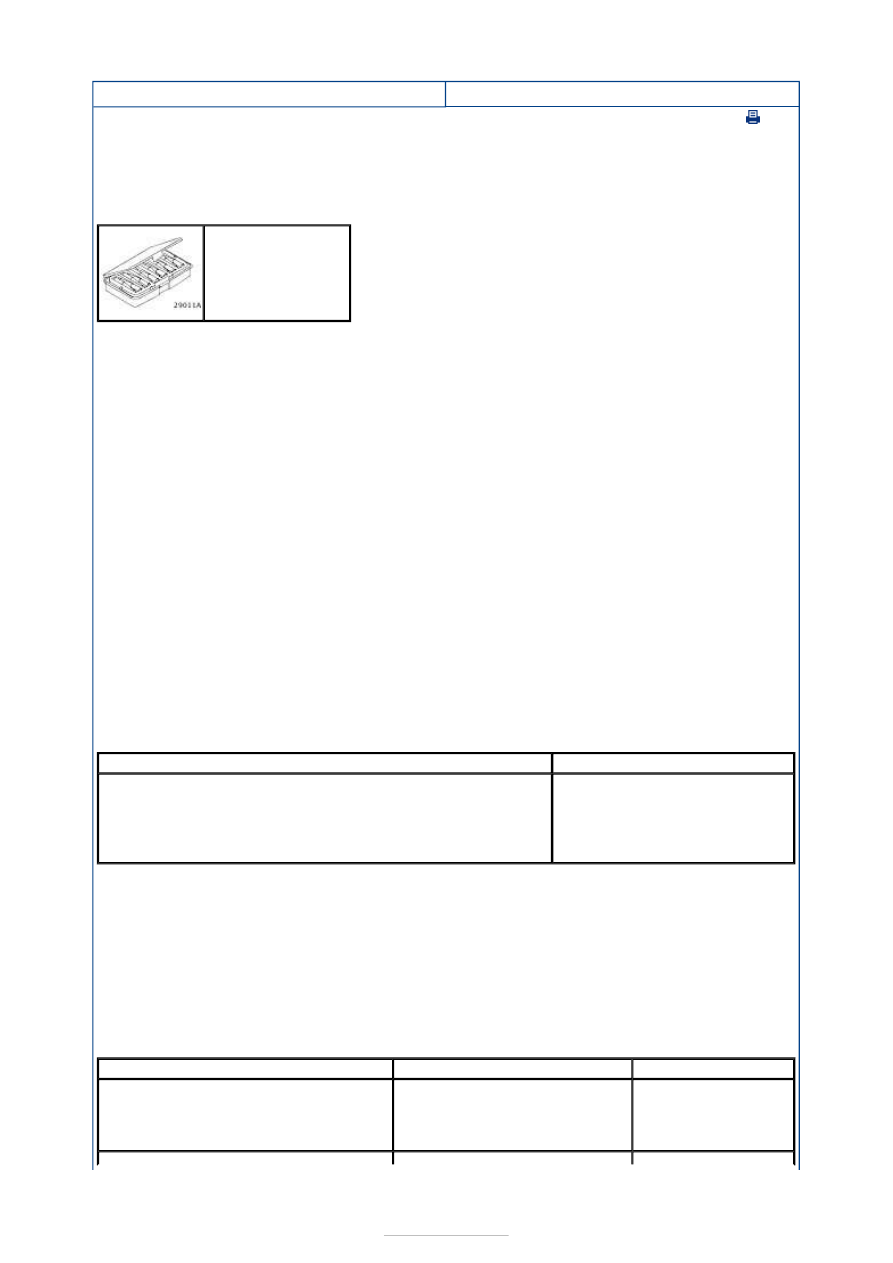
Terminal Probe Kit
29-011A
Mechanical
Electrical
stoplamp switch adjustment
Fuse(s)
Bulb(s)
Connector
Switch
Wiring loom
Symptom
Possible Sources
Action
The Stoplamps Are Inoperative
Fuse
Circuit(s)
Stoplamp switch
Smart Junction Box
*
*
*
*
GO to Pinpoint
Test
A.
*