Ford Galaxy / Ford S-MAX. Manual - part 763
 

  Index      Ford     Ford Galaxy / Ford S-MAX - service repair manual 2006 year


Search            


Content   ..  761  762  763  764   ..


Ford Galaxy / Ford S-MAX. Manual - part 763


Component Checks 

High beam headlamp switch 

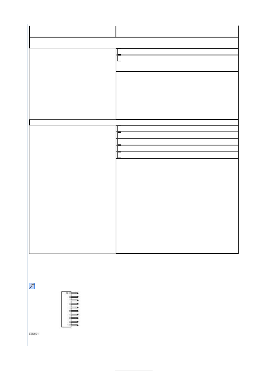
Pin occupation, component side: 

NOTE: The value measured in the continuity test of the high beam switch should be less 

headlamp with the aid of the Wiring Diagrams. 
CHECK system operates correctly 

H14: CHECK THE GROUND CONNECTION OF THE CORNERING LIGHT, RIGHT-HAND 
HEADLAMP, FOR OPEN CIRCUIT

Ignition switch in position 0. 

Measure the resistance between the left-hand 
headlamp, connector C1LF09, pin 9, circuit 

GD132X (BK/VT), wiring harness side and ground. 

Is a resistance of less than 2 Ohms registered? 
Yes 

INSTALL A NEW headlamp. CHECK system operates 
correctly 

No 

LOCATE and RECTIFY the break in corresponding 
circuit GD132X (BK/VT) between soldered 
connection SP380 and the headlamp using the 
Wiring Diagrams. CHECK system operates correctly 

H15: RULE OUT THE ADAPTIVE LIGHTING MODULE AS THE CAUSE OF THE FAULT

Ignition switch in position 0. 

Disconnect fuse F39 (15 A) (EJB). 

Disconnect fuse F43 (5 A) (EJB). 

Ignition switch in position II. 

CHECK the cornering lights. 

Is the left-hand cornering light permanently on? 
Yes 

LOCATE and RECTIFY the short to battery voltage 
in the circuits between the adaptive lighting module 
and the left-hand headlamp with the aid of the 
Wiring Diagrams. CHECK system operates correctly 

No 

- Right-hand cornering light permanently lit: 
LOCATE and RECTIFY the short to battery voltage 
in the circuits between the adaptive lighting module 
and the right-hand headlamp with the aid of the 
Wiring Diagrams. CHECK system operates correctly 
- None of the cornering lights is permanently lit: 
RENEW the adaptive front lighting module. CHECK 
system operates correctly If the concern persists:  
REFER to: 

Communications Network

 (418-00 

Module Communications Network, Diagnosis and 
Testing). 


than 50 Ohm. 

Circuit to test

Connect a digital multimeter 

with the following 

connections

Set the switch to 

the following 

position

Switch is OK when the 

following test readings 

are seen

Headlamp 

flasher

1 and 3

Off

Open circuit

On

Closed circuit

High beam

1 and 6

Off

Open circuit

On

Closed circuit

Left-hand turn 

signal

1 and 5

Neutral position

Open circuit

On

Closed circuit

Right-hand 

turn signal

1 and 4

Neutral position

Open circuit

On

Closed circuit

Exterior Lighting - Autolamps

S-MAX/Galaxy 2006.5 (02/2006-)


Print


Diagnosis and Testing 

Refer to Wiring Diagrams Section 417-01, for schematic and connector 
information.  

Special Tool(s) 

Inspection and Testing 

NOTE: The generic electronic module (GEM) is part of the central junction box (CJB). 
NOTE: If a new generic electronic module (GEM) is being installed, the new module must 
be configured following installation. For this purpose, the vehicle-specific data or the data 
to be changed is read out of the module using WDS and is transferred to the new module.  
NOTE: Before reading out the vehicle-specific data make sure that all electrical 
connections in the vehicle are reconnected so that the module and WDS can communicate 
correctly. 
NOTE: Ensure correct locking of the wiring harness connector. 
NOTE: The rain sensor module is also responsible for actuating the automatic headlamps. 

1. 1. Verify the customer concern. 

2. 2. Visually inspect for obvious signs of electrical (or mechanical) damage. 

Visual Inspection 

3. 3. Resolve any obvious causes or concerns found during the visual inspection before 

carrying out any further tests. 

4. 4. If the concern is not visually evident, PERFORM a fault diagnosis on the generic 

electronic module (GEM) with WDS and RECTIFY any displayed faults in accordance 
with the displayed fault description. CHECK the operation of the system. 

5. 5. On a vehicle without stored fault(s), continue according to the Symptom Chart and 

the corresponding symptom. 

6. 6. Following checking or elimination of the fault(s) and after completion of operations, 

the fault memory in the generic electronic module (GEM) must be READ OUT and 
any stored faults must be DELETED. After road testing and CHECKING the system, 
READ OUT the fault memory again. 

Terminal Probe Kit 

29-011A 

Mechanical

Electrical

Check the adhesive pad between the rain sensor and the windshield 

for trapped air.  

Clean wax residues from the windshield in the vicinity of the rain 

sensor.  

Check the windshield for damage/cracks in the vicinity of the rain 

sensor.  

Check that the rain sensor retaining frame is correctly attached to the 

windshield.  

Check the wiper blades for residue-free wiping in the vicinity of the 

rain sensor. 

Fuse(s)  

Bulb(s)  

Connector  

Switch  

Wiring 

loom 


Diagnostic Trouble Code (DTC) Table - Generic Electronic Module (GEM) 

Symptom Chart 

Pinpoint Tests 

NOTE: Use a digital multimeter for all measurements. 

DTC

Description

Action

B10AD-04

Rain sensor, internal system fault

GO to Pinpoint Test 

A. 

B10AD-09

Rain sensor, component fault

GO to Pinpoint Test 

A. 

Symptom

Possible Sources

Action

Automatic headlamps inoperative

Fuse 
BJB 
Circuit(s) 
Lighting control module 

(LCM) 

Rain sensor 

*
*
*
*

*

GO to Pinpoint Test 

A. 


*

Automatic headlamps on 
permanently

Circuit(s) 
BJB 
Lighting control module 

(LCM) 

Rain sensor 

*
*
*

*

GO to Pinpoint Test 

B. 


*

PINPOINT TEST A : AUTOMATIC HEADLAMPS INOPERATIVE 

TEST CONDITIONS

DETAILS/RESULTS/ACTIONS

A1: DETERMINE THE FAULT CONDITION

Ignition switch in position II. 

SWITCH ON dipped beam. 

CHECK the operation of the dipped beam and the 
parking lamps. 

SWITCH ON the automatic headlamps. 

Cover rain sensor with opaque material to simulate 
insufficient light conditions. 

CHECK the operation of the dipped beam and the 
parking lamps. 

Is the normal dipped beam operative? 
Yes 

Automatic headlamps inoperative: 

GO to A2

.  

No 

REFER to: 

Headlamps

 (417-01 Exterior Lighting, 

Diagnosis and Testing). 

A2: CHECK FUSE F1 (5 A) (CJB).

Ignition switch in position 0. 

Disconnect Fuse F1 (5 A) (CJB). 

CHECK Fuse F1 (5 A) (CJB). 

Is the fuse OK.? 
Yes 

GO to A3

.  

No 

RENEW fuse F1 (5 A) (CJB) and CHECK the 
operation of the system. If the fuse blows again, 
LOCATE and RECTIFY the short to ground using the 
Wiring Diagrams. CHECK the operation of the 
system. 

A3: CHECK THE VOLTAGE SUPPLY TO FUSE F1 (5 A) (CJB) FOR OPEN CIRCUIT

Connect Fuse F1 (5 A) (CJB). 

Ignition switch in position II. 


Content   ..  761  762  763  764   ..