Ford Galaxy / Ford S-MAX. Manual - part 715
 

  Index      Ford     Ford Galaxy / Ford S-MAX - service repair manual 2006 year


Search            


Content   ..  713  714  715  716   ..


Ford Galaxy / Ford S-MAX. Manual - part 715


Is a voltage present? 
Yes 

REPAIR the circuit. TEST the system for normal 
operation. 

No 

INSTALL a new front parking aid speaker. TEST the 
system for normal operation. If the concern persists, 
INSTALL a new parking aid module.  
REFER to: 

Parking Aid Module

 (413-13 Parking Aid, 

Removal and Installation). 
TEST the system for normal operation. 

PINPOINT TEST U : DTC B1B5411 - PARKING AID STATUS LED - SHORT TO 
GROUND 

TEST CONDITIONS

DETAILS/RESULTS/ACTIONS

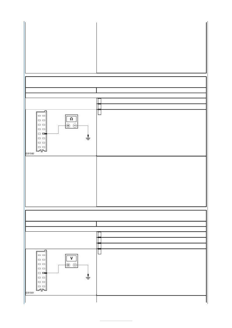
U1: CHECK CIRCUIT CMP02 (GN/BU) FOR OPEN

Disconnect Parking aid module C4MP01A. 

Disconnect Parking aid switch C2CA1S. 

Measure the resistance between the parking aid 
module C4MP01A pin 13, circuit CMP02A (GN/BU), 

harness side and ground. 

Is the resistance greater than 10,000 Ohms? 
Yes 

INSTALL a new parking aid switch. TEST the system 
for normal operation. If the concern persists, 
INSTALL a new parking aid module.  
REFER to: 

Parking Aid Module

 (413-13 Parking Aid, 

Removal and Installation). 
TEST the system for normal operation. 

No 

REPAIR the circuit. TEST the system for normal 
operation. 

PINPOINT TEST V : B1B5412 - PARKING AID STATUS LED - SHORT TO 
POWER 

TEST CONDITIONS

DETAILS/RESULTS/ACTIONS

V1: CHECK CIRCUIT CMP02 (GN/BU) FOR SHORT TO POWER

Disconnect Parking aid module C4MP01A. 

Disconnect Parking aid switch C2CA1S. 

Ignition switch in position II. 

Measure the voltage between the parking aid module 
C4MP01A pin 13, circuit CMP02A (GN/BU), harness 

side and ground. 

Is a voltage present? 


Yes 

REPAIR the circuit. TEST the system for normal 
operation. 

No 

INSTALL a new parking aid switch. TEST the system 
for normal operation. If the concern persists, 
INSTALL a new parking aid module.  
REFER to: 

Parking Aid Module

 (413-13 Parking Aid, 

Removal and Installation). 
TEST the system for normal operation. 

PINPOINT TEST W : DTC B1B5711 - FRONT PARKING AID SENSORS - 
POWER SUPPLY CIRCUIT SHORT TO GROUND 

TEST CONDITIONS

DETAILS/RESULTS/ACTIONS

W1: CHECK CIRCUIT LMP06 (VT/GY) FOR OPEN

Disconnect Front outer right parking aid sensor 
C1MP13. 

Disconnect Front inner right parking aid sensor 
C1MP12. 

Disconnect Front outer left parking aid sensor 
C1MP11. 

Disconnect Front inner left parking aid sensor 
C1MP10. 

Disconnect Parking aid module C4MP01B. 

Measure the resistance between the parking aid 
module C4MP01B pin 2, circuit LMP06A (VT/GY), 

harness side and the following electrical connectors. 

Front outer right parking aid sensor C1MP13 pin 1, 
circuit LMP06C (VT/GY), harness side. 

Front inner right parking aid sensor C1MP12 pin 1, 
circuit LMP06F (VT/GY), harness side. 

Front outer left parking aid sensor C1MP11 pin 1, 
circuit LMP06E (VT/GY), harness side. 

Front inner left parking aid sensor C1MP10 pin 1, 
circuit LMP06G (VT/GY), harness side. 

Are the resistances less than 1 Ohm? 
Yes 

INSTALL a new parking aid sensor(s) as required.  
REFER to: 

Front Parking Aid Sensor

 (413-13 Parking 

Aid, Removal and Installation). 
TEST the system for normal operation. If the concern 
persists, INSTALL a new parking aid module.  
REFER to: 

Parking Aid Module

 (413-13 Parking Aid, 

Removal and Installation). 
TEST the system for normal operation. 

No 

REPAIR the circuit(s). TEST the system for normal 
operation. 

PINPOINT TEST X : DTC B1B5811 - REAR PARKING AID SENSORS - POWER 
SUPPLY CIRCUIT SHORT TO GROUND 

TEST CONDITIONS

DETAILS/RESULTS/ACTIONS

X1: CHECK CIRCUIT LMP07 (BU/WH) FOR OPEN

Disconnect Rear outer right parking aid sensor 


C1MP17. 

Disconnect Rear inner right parking aid sensor 
C1MP16. 

Disconnect Rear outer left parking aid sensor 
C1MP15. 

Disconnect Rear inner left parking aid sensor 
C1MP14. 

Disconnect Parking aid module C4MP01C. 

Measure the resistance between the parking aid 
module C4MP01C pin 11, circuit LMP07A (BU/WH), 

harness side and the following electrical connectors. 

Rear outer right parking aid sensor C1MP17 pin 1, 
circuit LMP07F (BU/WH), harness side. 

Rear inner right parking aid sensor C1MP16 pin 1, 
circuit LMP07E (BU/WH), harness side. 

Rear outer left parking aid sensor C1MP15 pin 1, 
circuit LMP07B (BU/WH), harness side. 

Rear inner left parking aid sensor C1MP14 pin 1, 
circuit LMP07D (BU/WH), harness side. 

Are the resistances less than 1 Ohm? 
Yes 

INSTALL a new parking aid sensor(s) as required.  
REFER to: 

Rear Parking Aid Sensor

 (413-13 Parking 

Aid, Removal and Installation). 
TEST the system for normal operation. If the concern 
persists, INSTALL a new parking aid module.  
REFER to: 

Parking Aid Module

 (413-13 Parking Aid, 

Removal and Installation). 
TEST the system for normal operation. 

No 

REPAIR the circuit(s). TEST the system for normal 
operation. 

PINPOINT TEST Y : DTC U300362 - MIS-MATCH IN BATTERY VOLTAGE 
BETWEEN THE PARKING AID MODULE AND THE CJB 

TEST CONDITIONS

DETAILS/RESULTS/ACTIONS

Y1: CHECK CIRCUIT CBR01AWA (BU) FOR POWER

Disconnect Parking aid module C4MP01A. 

Ignition switch in position II. 

Measure the voltage between the parking aid module 
C4MP01A pin 1, circuit CBR01AWA (BU), harness 

side and ground. 

Is the voltage greater than 10 volts? 
Yes 

GO to Y2

.  

No 

REPAIR the circuit. TEST the system for normal 


operation. If the concern persists,  
REFER to: 

Communications Network

 (418-00 Module 

Communications Network, Diagnosis and Testing). 

Y2: CHECK CIRCUIT GD152 (BK/BU) FOR OPEN

Ignition switch in position 0. 

Measure the resistance between the parking aid 
module C4MP01A pin 8, circuit GD152 (BK/BU), 

harness side and ground. 

Is the resistance less than 1 Ohm? 
Yes 

INSTALL a new parking aid module.  
REFER to: 

Parking Aid Module

 (413-13 Parking Aid, 

Removal and Installation). 
TEST the system for normal operation. 

No 

CLEAN and TIGHTEN the ground connection. TEST 
the system for normal operation. If the concern 
persists, REPAIR the circuit. TEST the system for 
normal operation. 


Content   ..  713  714  715  716   ..