Ford Galaxy / Ford S-MAX. Manual - part 701
 

  Index      Ford     Ford Galaxy / Ford S-MAX - service repair manual 2006 year


Search            


Content   ..  699  700  701  702   ..


Ford Galaxy / Ford S-MAX. Manual - part 701


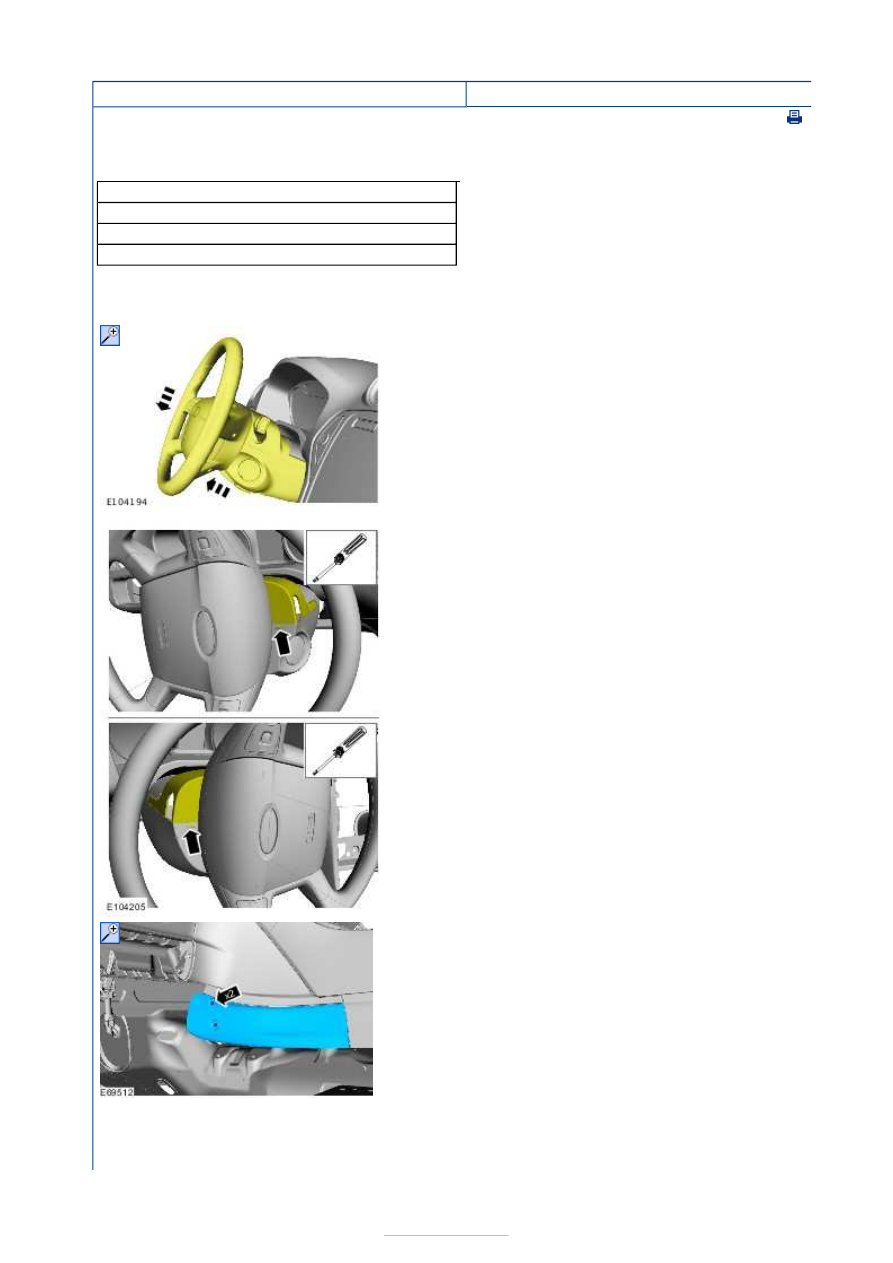
Instrument Cluster - Instrument Cluster

S-MAX/Galaxy 2006.5 (02/2006


Print

Removal and Installation 

General Equipment 

Removal 

NOTE: Removal steps in this procedure may contain installation details. 

Cable ties
Flat-bladed screwdriver
Ford diagnostic equipment
Round-ended steel rule

1.  

2. General Equipment: 

Flat-bladed screwdriver


3.  

4.  


5.  

6. Torque: 8 Nm 

7.  

8.

CAUTION: Make sure that no strain is placed 

on the wiring harnesses. 

General Equipment: 

Cable ties


9.  


Installation 

10. General 

Equipment: 

Round-
ended steel 
rule


1. To install, reverse the removal procedure. 

2.

NOTE: The central car configuration data must be 
manually uploaded after the installation of a new 
instrument cluster.  

For additional information due to module configuration 
see TSB 73/2006. 

General Equipment: 

Ford diagnostic equipment


Horn - Horn

S-MAX/Galaxy 2006.5 (02/2006-)


Print


Diagnosis and Testing 

Principles of Operation 

The horn system consists of a relay, a steering wheel switch and either one or two horns. 
The horn(s) receives voltage from the switched side of the relay, and the relay switch is 
controlled on its ground side by the steering wheel switch. 

The horn relay, is located in the battery junction box (BJB) and is supplied with a 
permanent voltage from the battery. 

The steering wheel horn switch shares the steering wheel clockspring circuit with the air-
bag circuit. Each of these systems work completely independent of each other. 

Inspection and Verification 

1. 1. Verify the customer concern. 

2. 2. Visually inspect for obvious signs of mechanical or electrical damage. 

Visual Inspection Chart 

3. 3. If an obvious cause for an observed or reported concern is found, correct the cause 

(if possible) before proceeding to the next step. 

4. 4. Retrieve the Diagnostic Trouble Code (DTC)s and refer to the DTC Index Chart. 

Diagnostic Trouble Code (DTC) Index Chart 

1. 1. If the cause is still evident, refer to the Symptom Chart. 

Symptom Chart 

Electrical

Fuse(s)  

Wiring harness  

Electrical connector(s)  

Horn switch  

Horn  

Clockspring  

Horn relay  

BJB 

DTC

Description/Condition

Possible 

Source

Action

9C5512

Horn relay- circuit short to battery

BJB

REFER to Ford diagnostic 

equipment.

9C5514 Horn relay - circuit short to ground or 

open

BJB

REFER to Ford diagnostic 

equipment.

Symptom

Possible Sources

Action

The horn is inoperative

Circuit(s). 
Horn. 
Horn relay. 
Clockspring. 
Horn switch. 
BJB. 

*
*
*
*
*
*

GO to Pinpoint Test 

A. 


*


Content   ..  699  700  701  702   ..