Ford Galaxy / Ford S-MAX. Manual - part 702
 

  Index      Ford     Ford Galaxy / Ford S-MAX - service repair manual 2006 year


Search            


Content   ..  700  701  702  703   ..


Ford Galaxy / Ford S-MAX. Manual - part 702


Pinpoint Tests 

The horn is always on

Horn relay. 
BJB. 
Horn switch. 
Circuit(s). 
Clockspring. 

*
*
*
*
*

REFER to the Ford diagnostic equipment. 

*

PINPOINT TEST A : THE HORN IS INOPERATIVE 

TEST CONDITIONS

DETAILS/RESULTS/ACTIONS

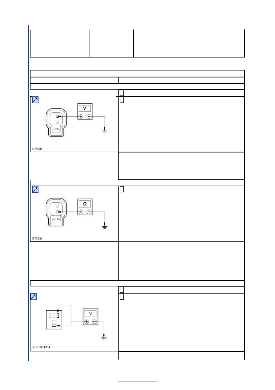
A1: CHECK POWER TO THE HORN

Disconnect Horn C1RH02. 

Measure the voltage between the horn C1RH02 pin 
2, circuit GBB31B (BU/OG), harness side and 

ground while pressing the horn switch. 

Is the voltage greater than 10 volts? 
Yes 

GO to A2

.  

No 

GO to A3

.  

A2: CHECK GROUND TO THE HORN

Measure the resistance between the horn C1RH02 
pin 1, circuit GD312G (BK/VT), harness side and 

ground. 

Is the resistance less than 5 ohms? 
Yes 

INSTALL a new horn. TEST the system for normal 
operation. 

No 

REPAIR circuit GD312G (BK/VT). TEST the system 
for normal operation. 

A3: CHECK POWER TO THE HORN RELAY

Disconnect Horn Relay R9. 

Measure the voltage between the horn relay R9 pin 
1, harness side and ground; and horn relay R9 pin 

3, harness side and ground. 

Are the voltages greater than 10 volts? 


Yes 

GO to A4

.  

No 

INSTALL a new BJB. TEST the system for normal 
operation. 

A4: CHECK HORN SWITCH CIRCUIT FOR OPEN

Measure the resistance between the horn relay R9 
pin 2, circuit CRH04A (VT/GN), harness side and 

ground while pressing the horn switch. 

Is the resistance less than 5 ohms? 
Yes 

INSTALL a new horn Relay R9. Test the system for 
normal operation. 

No 

GO to A5

.  

A5: CHECK SUPPLY TO THE CJB

Disconnect CJB 1BB01. 

Measure the voltage between the CJB 1BB01 pin 1, 
harness side and ground and between the CJB 

1BB01 pin 2, harness side and ground. 

Are the voltages greater than 10 volts? 
Yes 

REPAIR the circuit SBB17. TEST the system for 
normal operation. 

No 

GO to A6

.  

A6: CHECK CIRCUIT CRH04A (BN) FOR OPEN

Measure the resistance between the CJB 1BB01 pin 
46 component side and ground while pressing the 

horn switch. 

Is the resistance less than 5 ohms? 
Yes 

REPAIR the circuit CRH04A. TEST the system for 
normal operation. 

No 

GO to A7

.  

A7: CHECK CJB 1BB01 FOR OPEN

Measure the resistance between the CJB 1BB01 pin 
13, harness side and ground while pressing the 


horn switch. 

Is the resistance less than 5 ohms? 
Yes 

INSTALL a new CJB 1BB01. Test the system for 
normal operation. 

No 

GO to A8

.  

A8: CHECK CIRCUIT CRH03A (BN) FOR OPEN

WARNING: To deactivate the driver air bag, refer to the procedure in section 501-

20B. Failure to follow this instruction, may result in personal injury. 

Disconnect steering wheel module 2R115. 

Measure the resistance between the steering wheel 
module 2R115 pin 4, circuit CRH03-A (BN), harness 

side and horn relay R9 pin 2, CRH03-A (BN), 
harness side. 

Is the resistance less than 5 ohms? 
Yes 

GO to A9

.  

No 

REPAIR the circuit CRH03-A. TEST the system for 
normal operation. 

A9: CHECK CIRCUIT GD133CJ (BK) FOR OPEN

Measure the resistance between the steering wheel 
module 2R115 pin 7, circuit GD133CJ (BK), harness 

side and ground. 

Is the resistance less than 5 ohms? 
Yes 

GO to A10

.  

No 

REPAIR the circuit GD133CJ. TEST the system for 
normal operation. 

A10: CHECK CIRCUIT C2RH02AB FOR OPEN

Disconnect horn switch 2RH03. 

Measure the resistance between the steering wheel 
module 2R115 pin 7, circuit CRH02AB, harness side 

and horn switch 2RH03 pin 1, circuit C2RH02B, 
harness side. 


Is the resistance less than 5 ohms? 
Yes 

GO to A11

.  

No 

REPAIR the circuit C2RH02AB. TEST the system for 
normal operation. 

A11: CHECK THE HORN SWITCH

Measure the resistance between the horn switch 
2RH03 pin 1, component side and horn switch 

2RH03 pin 2, component side while pressing the 
horn switch. 

Is the resistance less than 5 ohms? 
Yes 

GO to A12

.  

No 

INSTALL a new horn switch 2RH03. TEST the 
system for normal operation. 

A12: CHECK CIRCUIT C2RH03AB FOR OPEN

Measure the resistance between the steering wheel 
module pin 4, circuit CRH03AB, harness side and 

horn switch C2RH03 pin 2, circuit C2RH03AB, 
harness side. 

Is the resistance less than 5 ohms? 
Yes 

INSTALL a new steering wheel module. TEST the 
system for normal operation. 

No 

REPAIR the circuit C2RH03AB. TEST the system for 
normal operation. 


Content   ..  700  701  702  703   ..