Ford Galaxy / Ford S-MAX. Manual - part 656
 

  Index      Ford     Ford Galaxy / Ford S-MAX - service repair manual 2006 year


Search            


Content   ..  654  655  656  657   ..


Ford Galaxy / Ford S-MAX. Manual - part 656


harness side. 

Is a resistance of less than 2 Ohms registered? 
Yes 

CHECK the auxiliary climate control module using 
WDS, RENEW if necessary. 

No 

LOCATE and RECTIFY the break in circuit VHA31A 
(GN/BN) between the auxiliary climate control air 
outlet temperature sensor and the auxiliary climate 
control module using the Wiring Diagrams. CHECK 
the operation of the system. 

D3: CHECK GROUND CONNECTION FROM AUXILIARY CLIMATE CONTROL AIR OUTLET 
TEMPERATURE SENSOR

Ignition switch in position 0. 

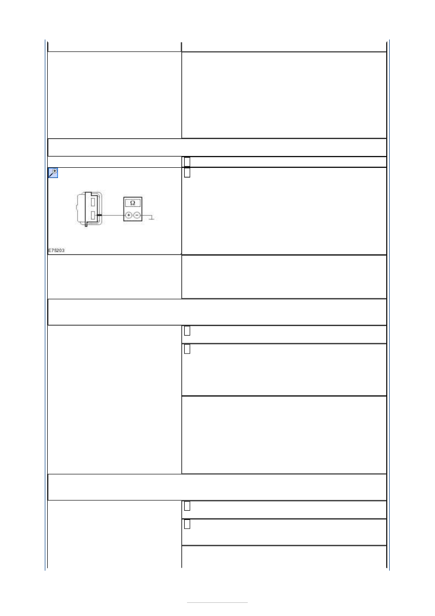
Measure the resistance between the auxiliary climate 
control air outlet temperature sensor, connector 

C4HA09-A, pin 2, circuit RHA27A (GY/BU), wiring 
harness side and ground. 

Is a resistance of less than 2 Ohms registered? 
Yes 

GO to D5

.  

No 

GO to D4

.  

D4: CHECK CIRCUIT BETWEEN AUXILIARY CLIMATE CONTROL AIR OUTLET 
TEMPERATURE SENSOR AND AUXILIARY CLIMATE CONTROL MODULE FOR OPEN 
CIRCUIT

Disconnect Connector C3H101-R from auxiliary 
climate control module. 

Measure the resistance between the auxiliary climate 
control air outlet temperature sensor, connector 

C4HA09-A, pin 2, circuit RHA27A (GY/BU), wiring 
harness side and the auxiliary climate control 
module, connector C3H101-R, pin 14, circuit RHA27A 
(GY/BU), wiring harness side. 

Is a resistance of less than 2 Ohms registered? 
Yes 

GO to D5

.  

No 

LOCATE and RECTIFY the break in circuit RHA27A 
(GY/BU) between the auxiliary climate control air 
outlet temperature sensor and the auxiliary climate 
control module using the Wiring Diagrams. CHECK 
the operation of the system. 

D5: CHECK CIRCUIT BETWEEN AUXILIARY CLIMATE CONTROL AIR OUTLET 
TEMPERATURE SENSOR AND AUXILIARY CLIMATE CONTROL MODULE FOR SHORT TO 
GROUND

Disconnect Connector C3H101-R from auxiliary 
climate control module. 

Measure the resistance between the auxiliary climate 
control module, connector C3H101-R, pin 14, circuit 

RHA27A (GY/BU), wiring harness side and ground. 

Is a resistance of more than 10,000 Ohm measured? 
Yes 


Component Tests 

Blower relay, auxiliary climate control 

1. 1. Check the normally open contact in the unswitched state: 

1. Measure the resistance at the auxiliary climate control blower relay, between pin 3 

and pin 5, component side. 

2. Is a resistance of more than 10,000 Ohm measured? 
3. If yes, goto 2. 
4. If no, RENEW the auxiliary climate control blower relay. 

2. 2. Check the normally open contact in the switched state: 

1. Using a fused test cable (1 A), connect pin 1 of the auxiliary climate control blower 

relay, component side, to the battery positive terminal. 

2. Using a test cable, connect pin 2 of the auxiliary climate control blower relay, 

component side, with the battery negative pole. 

3. Measure the resistance at the auxiliary climate control blower relay, between pin 3 

and pin 5, component side. 

4. Is a resistance of less than 2 Ohms registered? 
5. If yes, then the auxiliary climate control blower relay is OK. 
6. If no, RENEW the auxiliary climate control blower relay. 

RENEW the auxiliary climate control air outlet 
temperature sensor. CHECK the operation of the 
system. 

No 

LOCATE and RECTIFY the short to ground in circuit 
RHA27A (GY/BU) between the auxiliary climate 
control module and the auxiliary climate control air 
outlet temperature sensor using the Wiring 
Diagrams. CHECK the operation of the system. 


Climate Control System - General 
Information - Air Conditioning (A/C) 
Clutch Air Gap Adjustment

S-MAX/Galaxy 2006.5 (02/2006-)


Print


General Procedures 

1. Check the gap A (measure the difference 

between the engaged and disengaged positions 
of the air conditioning clutch) at 60° intervals 
around the circumference of the pulley. Operate 
the air conditioning clutch several times with the 
aid of a 5 A fused cable. Refer to the relevant 
wiring diagram for the correct electrical 
connection. 

Refer to: 

Specifications

 (412-00 Climate Control 

System - General Information, Specifications). 

2.  

3. If necessary correct the gap A using spacer 

washers. 

4. Refer to: 

Specifications

 (412-00 Climate Control 

System - General Information, Specifications). 

5. Check the gap A as described in step 1. If 

necessary, repeat steps 2-5. 


Climate Control System - General 
Information - Air Conditioning (A/C) 
System Recovery, Evacuation and 
Charging

S-MAX/Galaxy 2006.5 (02/2006-)


Print


General Procedures 

General Equipment 

Vehicles with 2.0L engine 

Vehicles with a diesel engine 

All vehicles 

Adapter for air conditioning service unit
Air conditioning service unit
Automatic calibration halogen leak detector
Electronic leak detector
UV leak detector

1. Refer to: 

Air Conditioning (A/C) System Health 

and Safety Precautions

 (100-00 General 

Information, Description and Operation). 

2.  

3.  

4.   

1. Low pressure filling connection 
2. High pressure filling connection 


Content   ..  654  655  656  657   ..