Ford Galaxy / Ford S-MAX. Manual - part 654
 

  Index      Ford     Ford Galaxy / Ford S-MAX - service repair manual 2006 year


Search            


Content   ..  652  653  654  655   ..


Ford Galaxy / Ford S-MAX. Manual - part 654


side. 

Is a resistance of less than 2 Ohms registered? 
Yes 

CHECK RJB and RENEW if necessary. CHECK the 
operation of the system. 

No 

LOCATE and RECTIFY the break in the circuit 
between the RJB and the auxiliary climate control 
module using the Wiring Diagrams. CHECK the 
operation of the system. 

B7: CHECK THE GROUND CONNECTION OF THE AUXILIARY CLIMATE CONTROL 
MODULE

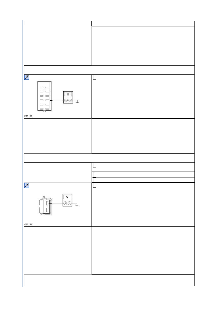
Measure the resistance between the auxiliary climate 
control module, connector C3H101-A, pin 10, circuit 

GD150L (BK/WH), wiring harness side and ground. 

Is a resistance of less than 2 Ohms registered? 
Yes 

GO to B8

.  

No 

LOCATE and RECTIFY the break in the circuit 
between the auxiliary climate control module and 
ground connection G4D149 using the Wiring 
Diagrams. CHECK the operation of the system. 

B8: CHECK VOLTAGE AT AUXILIARY CLIMATE CONTROL EVAPORATOR TEMPERATURE 
SENSOR

Disconnect Connector C4HA30 from auxiliary climate 
control evaporator temperature sensor. 

Ignition switch in position II. 

SWITCH ON auxiliary climate control. 

Measure the voltage between the auxiliary climate 
control evaporator temperature sensor, connector 

C4HA30, pin 1, circuit VHA30A (BN/YE), wiring 
harness side and ground. 

Is a voltage of approx. 5 volts measured? 
Yes 

GO to B11

.  

No 

- The voltage measured is more than 6 Volts:LOCATE 
and RECTIFY the short to voltage in circuit VHA30A 
(BN/YE) between the auxiliary climate control module 
and the auxiliary climate control evaporator 
temperature sensor using the Wiring Diagrams. 
CHECK the operation of the system. 
- No voltage measured:

GO to B9

.  

B9: CHECK THE CIRCUIT BETWEEN THE AUXILIARY CLIMATE CONTROL EVAPORATOR 
TEMPERATURE SENSOR AND THE AUXILIARY CLIMATE CONTROL MODULE FOR 


SHORT CIRCUIT TO GROUND

Ignition switch in position 0. 

Disconnect Connector C3H101-R from auxiliary 
climate control module. 

Measure the resistance between the auxiliary climate 
control evaporator temperature sensor, connector 

C4HA30, pin 1, circuit VHA30A (BN/YE), wiring 
harness side and ground. 

Is a resistance of more than 10,000 Ohm measured? 
Yes 

GO to B10

.  

No 

LOCATE and RECTIFY the short to ground in circuit 
VHA30A (BN/YE) between the auxiliary climate 
control module and the auxiliary climate control 
evaporator temperature sensor using the Wiring 
Diagrams. CHECK the operation of the system. 

B10: CHECK THE CIRCUIT BETWEEN THE AUXILIARY CLIMATE CONTROL 
EVAPORATOR TEMPERATURE SENSOR AND THE AUXILIARY CLIMATE CONTROL 
MODULE FOR OPEN CIRCUIT

Measure the resistance between the auxiliary climate 
control evaporator temperature sensor, connector 

C4HA30, pin 1, circuit VHA30A (BN/YE), wiring 
harness side and auxiliary climate control module, 
connector C3H101-R, pin 5, wiring harness side. 

Is a resistance of less than 2 Ohms registered? 
Yes 

CHECK the auxiliary climate control module using 
WDS, RENEW if necessary. 

No 

LOCATE and RECTIFY the break in circuit VHA30A 
(BN/YE) between the auxiliary climate control 
evaporator temperature sensor and the auxiliary 
climate control module using the Wiring Diagrams. 
CHECK the operation of the system. 

B11: CHECK GROUND CONNECTION FROM AUXILIARY CLIMATE CONTROL 
EVAPORATOR TEMPERATURE SENSOR

Ignition switch in position 0. 

Measure the resistance between the auxiliary climate 
control evaporator temperature sensor, connector 

C4HA30, pin 2, circuit RHA26A (BU/WH), wiring 
harness side and ground. 

Is a resistance of less than 2 Ohms registered? 
Yes 

RENEW auxiliary climate control evaporator 
temperature sensor. CHECK the operation of the 
system. 


No 

GO to B12

.  

B12: CHECK THE CIRCUIT BETWEEN THE AUXILIARY CLIMATE CONTROL 
EVAPORATOR TEMPERATURE SENSOR AND THE AUXILIARY CLIMATE CONTROL 
MODULE FOR OPEN CIRCUIT

Disconnect Connector C3H101-R from auxiliary 
climate control module. 

Measure the resistance between the auxiliary climate 
control evaporator temperature sensor, connector 

C4HA30, pin 2, circuit RHA26A (BU/WH), wiring 
harness side and auxiliary climate control module, 
connector C3H101-R, pin 15, wiring harness side. 

Is a resistance of less than 2 Ohms registered? 
Yes 

GO to B13

.  

No 

LOCATE and RECTIFY the break in circuit RHA26A 
(BU/WH) between the auxiliary climate control 
evaporator temperature sensor and the auxiliary 
climate control module using the Wiring Diagrams. 
CHECK the operation of the system. 

B13: CHECK VOLTAGE AT EXPANSION/CUT-OUT VALVE

Ignition switch in position 0. 

Connect Connector C3H101-R from auxiliary climate 
control module. 

Disconnect Connector C4HA28 from expansion/cut-
out valve. 

Ignition switch in position II. 

Measure the voltage between the expansion/cut-out 
valve, connector C4HA28, pin 2, circuit CHA28A 

(VT/OG), wiring harness side and ground. 

Does the meter display battery voltage? 
Yes 

GO to B16

.  

No 

GO to B14

.  

B14: CHECK THE CIRCUIT BETWEEN THE EXPANSION/CUT-OUT VALVE AND THE 
AUXILIARY CLIMATE CONTROL MODULE FOR SHORT CIRCUIT TO GROUND

Ignition switch in position 0. 

Disconnect Connector C3H101-R from auxiliary 
climate control module. 

Measure the resistance between the expansion/cut-
out valve, connector C4HA28, pin 2, circuit CHA28A 

(VT/OG), wiring harness side and ground. 

Is a resistance of more than 10,000 Ohm measured? 
Yes 

GO to B15

.  

No 

LOCATE and RECTIFY the short to ground in circuit 
CHA28A (VT/OG) between the auxiliary climate 
control module and the expansion/cut-out valve 
using the Wiring Diagrams. CHECK the operation of 
the system. 

B15: CHECK THE CIRCUIT BETWEEN THE EXPANSION/CUT-OUT VALVE AND THE 
AUXILIARY CLIMATE CONTROL MODULE FOR OPEN CIRCUIT

Measure the resistance between the expansion/cut-
out valve, connector C4HA28, pin 2, circuit CHA28A 

(VT/OG), wiring harness side and auxiliary climate 

control module, connector C3H101-R, pin 11, wiring 
harness side. 

Is a resistance of less than 2 Ohms registered? 
Yes 

CHECK the auxiliary climate control module using 
WDS, RENEW if necessary. 

No 

LOCATE and RECTIFY the break in circuit CHA28A 
(VT/OG) between the expansion/cut-out valve and 
the auxiliary climate control module using the Wiring 
Diagrams. CHECK the operation of the system. 

B16: CHECK GROUND CONNECTION FROM EXPANSION/CUT-OUT VALVE

Ignition switch in position 0. 

Measure the resistance between the expansion/cut-
out valve, connector C4HA28, pin 1, circuit RHA29A 

(WH/VT), wiring harness side and ground. 

Is a resistance of less than 2 Ohms registered? 
Yes 

RENEW expansion/cut-out valve. CHECK the 
operation of the system. 

No 

GO to B17

.  

B17: CHECK THE CIRCUIT BETWEEN THE EXPANSION/CUT-OUT VALVE AND THE 
AUXILIARY CLIMATE CONTROL MODULE FOR OPEN CIRCUIT

Disconnect Connector C3H101-R from auxiliary 
climate control module. 

Measure the resistance between the expansion/cut-
out valve, connector C4HA28, pin 1, circuit RHA29A 

(WH/VT), wiring harness side and auxiliary climate 
control module, connector C3H101-R, pin 10, wiring 
harness side. 

Is a resistance of less than 2 Ohms registered? 
Yes 

CHECK the auxiliary climate control module using 
WDS, RENEW if necessary. 

No 

LOCATE and RECTIFY the break in circuit RHA29A 
(WH/VT) between the expansion/cut-out valve and 
the auxiliary climate control module using the Wiring 
Diagrams. CHECK the operation of the system. 

PINPOINT TEST C : MALFUNCTION - AUXILIARY CLIMATE CONTROL 
TEMPERATURE CONTROL FLAP 

NOTE: Ensure that the auxiliary climate control temperature control flap is mechanically 
OK. 

TEST CONDITIONS

DETAILS/RESULTS/ACTIONS

C1: CHECK VOLTAGE AT AUXILIARY CLIMATE CONTROL TEMPERATURE CONTROL 
FLAP ACTUATOR

Ignition switch in position 0. 

Disconnect Connector C4HA20 from auxiliary climate 
control temperature control flap actuator. 

Ignition switch in position II. 

SWITCH ON auxiliary climate control. 

Measure the voltage between the auxiliary climate 
control temperature control flap actuator, connector 

C4HA20, pin 2, circuit CHA24A (WH/GN), wiring 
harness side and ground. 


Content   ..  652  653  654  655   ..