Ford Galaxy / Ford S-MAX. Manual - part 530
 

  Index      Ford     Ford Galaxy / Ford S-MAX - service repair manual 2006 year


Search            


Content   ..  528  529  530  531   ..


Ford Galaxy / Ford S-MAX. Manual - part 530


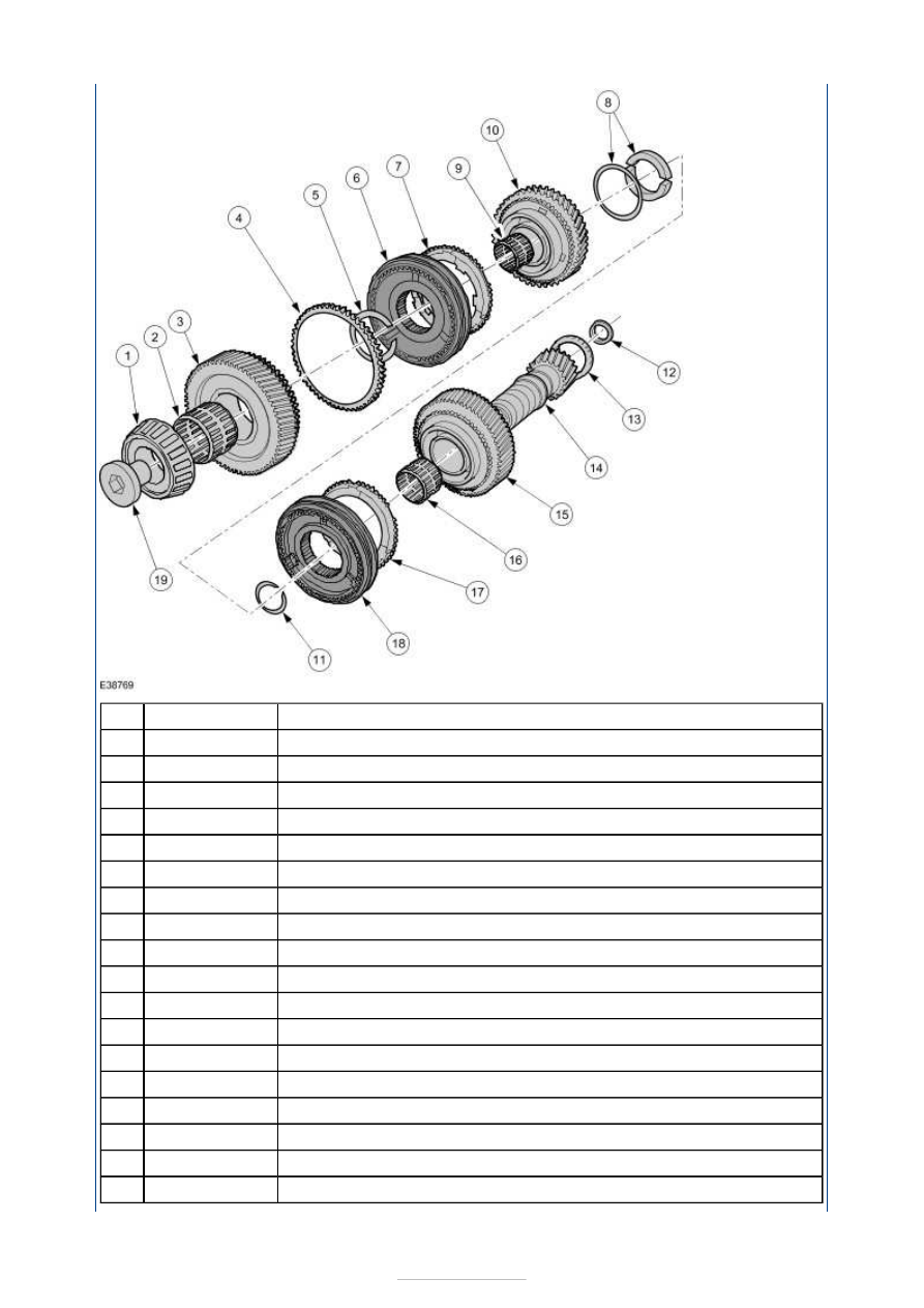
Description 

Transmission housing taper roller bearing 

Needle bearing 

6th gear wheel 

6th gear synchronizer ring 

Snap ring 

5th/6th gear synchronizer 

Synchronizer ring (5th gear) 

Stop disc unit 

Needle bearing 

5th gear wheel 

Snap ring 

Oil storage ring (until 10/2005) 

Clutch housing taper roller bearing 

Output shaft 5th/6th/reverse gear 

Reverse gear wheel 

Needle bearing 

Reverse gear synchronizer ring 

Reverse gear synchronizer 

Item

1

2

3

4

5

6

7

8

9

10

11

12

13

14

15

16

17

18


Part Number

-

-

-

-

-

-

-

-

-

-

-

-

-

-

-

-

-

-

-

Bearing retaining bolt (left-hand thread) 

Oil funnel and oil storage ring 

Until 10/2005 an oil storage ring was installed on the clutch side in each of the two output 
shafts. 


Description 

Oil funnel until 10/2005 

Oil storage ring until 10/2005 

Oil funnel from 11/2005 

When installing a new oil funnel, from 11/2005 onwards, an oil storage ring is no longer 
permitted, as this could lead to a loss of transmission fluid pressure in the output shaft and 
therefore to a loss of lubrication. 

Synchroniser assembly 


Description 

Sliding block assembly 

Synchroniser hub 

Sliding collar 

The (MMT6) synchroniser assemblies have been reworked for the 6-speed manual 
transmission. 

The detent balls, springs and sliding blocks form one unit. 

This arrangement makes it easier to service the synchroniser assembly. 

Differential 

Because the Vehicle Speed Sensor (VSS) is discontinued, so is the sender wheel. 

The ABS wheel speed sensors send the current wheel speed to the powertrain control 
module (PCM). 

19

Item

1

2

3

Item

1

2

3

-


Part Number

-

-

-


Part Number

-

-

-

The differential has taper roller bearings. 

This bearing arrangement requires the shaft to be preloaded. Please refer to the service 
literature for further information on how to measure the pre-load. 


Description 

Transmission housing taper roller bearing 

Differential 

Clutch housing taper roller bearing 

Crown wheel bolts 

Crown wheel 

Power transmission in the individual gears 

The following diagrams show a schematic representation of the power flow. 

Power is transmitted via the non-positive gear pair to the output pinion of the output shaft
(s) and thus to the differential ring gear. 

NOTE: The three shafts are shown away from their real positions for clarity. 

Power transmission route in 1st gear 

The 1st gear wheel is positively connected to the 1st to 4th gear output shaft by the 
1st/2nd gear synchroniser assembly. 

Power transmission route in second gear 

Item

1

2

3

4

5


Part Number

-

-

-

-

-


The 2nd gear wheel is positively connected to the 1st to 4th gear output shaft by the 
1st/2nd gear synchroniser assembly. 

Power transmission route in 3rd gear 

The 3rd gear wheel is positively connected to the 1st to 4th gear output shaft by the 
3rd/4th gear synchroniser assembly. 

Power transmission route in 4th gear 

The 4th gear wheel is positively connected to the 1st to 4th gear output shaft by the 
3rd/4th gear synchroniser assembly. 

Power transmission route in 5th gear 

The 5th gear wheel is positively connected to the 5th/6th/reverse gear output shaft by the 
5th/6th gear synchroniser assembly. 

Power transmission route in 6th gear 


Content   ..  528  529  530  531   ..