Ford Galaxy / Ford S-MAX. Manual - part 523
 

  Index      Ford     Ford Galaxy / Ford S-MAX - service repair manual 2006 year


Search            


Content   ..  521  522  523  524   ..


Ford Galaxy / Ford S-MAX. Manual - part 523


8.

NOTE: Do not oil the taper roller bearing. 

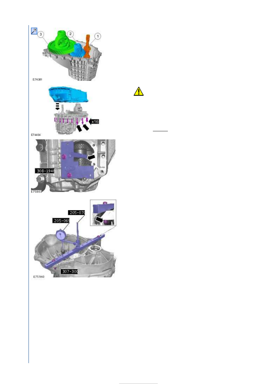
Install the following items: 

1.  
2.  
3.  

9.

CAUTION: The guide pins must remain installed 

in the gearbox housing. 
NOTE: The mounting faces of the component must 
be clean and free from foreign bodies and lubricant.

Tighten the bolts in a crisscross sequence. 

Torque: 

40 Nm 

10. Special Tool(s): 

308-194B


11. Install the Special Tool(s): 

205-069

205-070

307-300

12. Input shaft measurement: Carry out the following two 

steps three times and calculate the average of the 
measurements. (Example: (0.22 mm + 0.23 mm + 0.21 
mm) / 3 = 0.22 mm) 

13. Special Tool(s): 

205-175


14.   

1. Pre-load the dial gauge to 1 mm and zero it. 
2. Lift the input shaft with a suitable lever and note 

the resulting measurement. 

15. Output shaft measurement: Carry out the following three 

steps three times and calculate the average of the 
measurements. (Example: (0.32 mm + 0.33 mm + 0.31 
mm) / 3 = 0.32 mm) 

16. Special Tool(s): 

205-175


17. Attach the dial gauge, pre-load it to 1 mm and zero it.

Special Tool(s): 

205-069


18. Lift the output shaft with a suitable lever and note the 

resulting measurement. 


19. Install the Special Tool(s): 

303-060

303-060-02

303

060-07


20. Differential measurement: Carry out the following two 

steps three times and calculate the average of the 
measurements. (Example: (0.34 mm + 0.36 mm + 0.38 
mm) / 3 = 0.36 mm) 

21.   

1. Press down the differential during rotation. 

Special Tool(s): 

205-175


2. Pre-load the dial gauge to 1 mm and zero it. 

Special Tool(s): 

205-069


22. Lift the differential with the special tool and note the 

resulting measurement. 

Special Tool(s): 

303-060

303-060-02


23.   

Calculate the required adjusting shim thickness for 
the input shaft: 
Installed measuring shim thickness: 1.00 mm.
Calculated average input shaft end float e. g. 0.22 
mm. 
End float constant: -0.07 mm. 
Shim thickness required: 1.00 mm +0.22 mm 
0.07 mm = 1.15 mm 

24.   

Calculate the required adjusting shim thickness for 
the output shaft: 
Installed measurement shim thickness: 1.00 mm.
Calculated average output shaft end float, e.g.: 


0.32 mm. 
Pre-load constant 0.13 mm. 
Shim thickness required: 1.00 mm +0.32 mm 
+0.13 mm = 1.45 mm. 

25.   

Calculate the required adjusting shim thickness for 
the differential: 
Installed measurement shim thickness: 1.10 mm.
Calculated average differential end float e. g. 0.36 
mm. 
Pre-load constant 0.33 mm. 
Shim thickness required: 1.10 mm + 0.36 mm 
+0.33 mm = 1.79 mm. 

26. Remove the Special Tool(s): 

205-069

205-070

303

303-060-02

303-060-07

307-300

308-194B


27.  

28.  

29. Special Tool(s): 

205-176


30. Special Tool(s): 

205-078

205-078-01


Content   ..  521  522  523  524   ..