Ford Galaxy / Ford S-MAX. Manual - part 479
 

  Index      Ford     Ford Galaxy / Ford S-MAX - service repair manual 2006 year


Search            


Content   ..  477  478  479  480   ..


Ford Galaxy / Ford S-MAX. Manual - part 479


Electronic Engine Controls - 2.0L 
Duratorq-TDCi (85kW/115PS) - DW/2.0L 
Duratorq-TDCi (100kW/136PS) - 
DW/2.0L Duratorq-TDCi (103kW/140PS) 
- DW - Fuel Temperature Sensor

S-MAX/Galaxy 2006.5 (02/2006-)


Print


Removal and Installation 

Removal 

Installation 

1. Remove the intake manifold. 

Refer to: 

Intake Manifold

 (303-01F Engine - 2.0L 

Duratorq-TDCi (85kW/115PS) - DW/2.0L 
Duratorq-TDCi (100kW/136PS) - DW/2.0L 
Duratorq-TDCi (103kW/140PS) - DW, Emission 
Requirements: Stage IV, Removal and 
Installation). 

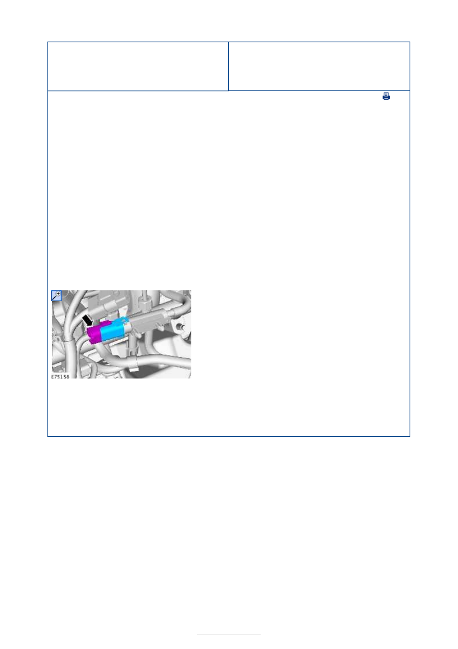
2. Clean the fuel temperature sensor and 

surrounding areas. 

Refer to: 

Fuel Injection Component Cleaning


(303-04D Fuel Charging and Controls - 1.8L 
Duratorq-TDCi (74kW/100PS) - Lynx/1.8L 
Duratorq-TDCi (92kW/125PS) - Lynx, General 
Procedures). 

3.  

1.

NOTE: Make sure that the sensor housing is 
clean and free of foreign material. 

To install, reverse the removal procedure.  


Electronic Engine Controls - 2.0L Duratorq-
TDCi (85kW/115PS) - DW/2.0L Duratorq-
TDCi (100kW/136PS) - DW/2.0L 
Duratorq-TDCi (103kW/140PS) - DW - 
Powertrain Control Module (PCM)

S-MAX/Galaxy 2006.5 (02/2006-)


Print


Removal and Installation 

General Equipment 

Removal 

Vehicles with PCM security shield 

3.5 mm drill bit
Center punch
Ford diagnostic equipment

1.

NOTE: This step is only necessary when 
installing a new component. 

Download the PCM and throttle body configuration 
information into the diagnostic tool, using the 
Programmable Modules Installation routine.  

General Equipment: 

Ford diagnostic equipment


2. Refer to: 

Battery Disconnect and Connect

 (414-01 

Battery, Mounting and Cables, General 
Procedures). 

3. Left-hand side wheel and tire. 

Refer to: 

Wheel and Tire

 (204-04 Wheels and 

Tires, Removal and Installation). 

4.  

5.  

6. Torque: 3 Nm 


Vehicles without PCM security shield 

Installation 

Vehicles with PCM security shield 

7. General 

Equipment: 

Center 
punch


General 
Equipment: 

3.5 mm 
drill bit


8.  

9. Torque: 3 Nm 

1. To install, reverse the removal procedure. 


All vehicles 

2. Tighten the shear bolt until the head is sheared 

off. 

3.

NOTE: This step is only necessary when 
installing a new component. 

Upload the PCM configuration information into the 
PCM, using the Programmable Modules Installation 
routine. 

General Equipment: 

Ford diagnostic equipment


Content   ..  477  478  479  480   ..